
Research on intelligent registration methods for multidimensional visual communication projection transform images
- Published
- Accepted
- Received
- Academic Editor
- Osama Sohaib
- Subject Areas
- Algorithms and Analysis of Algorithms, Computer Vision, Data Mining and Machine Learning, Optimization Theory and Computation, Neural Networks
- Keywords
- Multidimensional, Projection transformation, Image registration, LOG operator, Fourier descriptor, Mapping registration
- Copyright
- © 2025 Liang
- Licence
- This is an open access article distributed under the terms of the Creative Commons Attribution License, which permits unrestricted use, distribution, reproduction and adaptation in any medium and for any purpose provided that it is properly attributed. For attribution, the original author(s), title, publication source (PeerJ Computer Science) and either DOI or URL of the article must be cited.
- Cite this article
- 2025. Research on intelligent registration methods for multidimensional visual communication projection transform images. PeerJ Computer Science 11:e3147 https://doi.org/10.7717/peerj-cs.3147
Abstract
This article presents an intelligent image registration method tailored for images involved in multidimensional projection transformations in visual communication, which often suffer from blurred contours and incomplete shape alignments post-registration. The proposed approach comprises four integrated stages: (1) wavelet transform-based denoising for feature preservation, (2) edge detection using the Laplacian of Gaussian (LoG) operator, (3) contour matching via Fourier descriptors, and (4) projection and affine transformation for precise alignment. The method was evaluated on two high-resolution landscape datasets (Elephant Trunk Hill and Potala Palace, 1,920 × 1,080), achieving 99.1% accuracy and a root mean square error (RMSE) of 0.31. Compared to four state-of-the-art methods (DOI 10.1007/s10586-023-03974-3; DOI 10.1109/jsen.2023.3314608; DOI 10.1109/ACCESS.2023.3264968; DOI 10.1111/phor.12402), our approach demonstrated superior accuracy and execution speed. The technique is feasible for near real-time application on standard hardware (Intel i7 CPU, 16 GB RAM) and offers robustness without requiring supervised learning. This work contributes a clear, interpretable, and efficient framework for image registration.
Introduction
Image registration plays a foundational role in computer vision, enabling accurate alignment of images captured at varying times, angles, or by different sensors. Applications span across object classification, 3D reconstruction, medical imaging, and change detection. The registration task is particularly challenging when dealing with multidimensional visual communication projection images, which are prone to blurring, scale variance, and geometric distortions.
Conventional methods, such as speeded-up robust features + random sample consensus (SURF+RANSAC) (Arora, Mehta & Ahuja, 2023), Radon-based projection techniques (Hjouj, Jouini & Al-Khaleel, 2023), and synthetic aperture radar-scale-invariant feature transform (SAR-SIFT) with deep learning (Liaghat et al., 2023), have shown success but also present key limitations. While SURF combined with RANSAC is susceptible to noise and occlusion, the Radon transform exhibits limitations in detecting weak features (Elhani et al., 2023). Additionally, learning-based methods require extensive labeled datasets and substantial computational resources. Graph-based models, such as localization-weighted graph transformation matching (LWGTM) (Mohammadi, Sedaghat & Rad, 2022), improve outlier robustness but introduce additional complexity. These trade-offs between performance, interpretability, and generalization motivate the need for a more efficient and transparent registration method (Gildea, Hall & Mercadal-Baudart, 2023).
The proposed framework integrates Laplacian of Gaussian (LoG) edge detection, Fourier contour descriptors, and projection-based affine transformation into a unified pipeline, providing robust and interpretable image registration without the need for training data. Our key novelty lies in the tailored sequence of traditional, mathematically grounded tools that collectively achieve results comparable to or better than data-driven methods.
Regarding image registration work, relevant scholars have conducted extensive research, such as Arora, Mehta & Ahuja (2023) using a teaching and learning based optimization method to obtain the optimal values of rigid body transformation parameters, and then using the speeded-up robust feature (SURF) framework and random sample consistency (RANSAC) algorithm for feature extraction. Then use the projection transformation to obtain more accurately registered images. The RANSAC algorithm can eliminate incorrect matches, but its robustness may not be sufficient to ensure the correct matching of all feature points when dealing with images that contain a large amount of noise or occlusion. Mohammadi, Sedaghat & Rad (2022) first utilized the uniform robust accelerated robust feature (UR-SURF) algorithm to extract robust image features. Secondly, the rotation invariant self-similarity (RISS) descriptor is used, which is an inherent rotation-invariant descriptor based on the correlation value gradient direction histogram and has strong resistance to illumination differences. Building on this foundation, an enhanced variant of graph transformation matching—referred to as LWGTM—is employed to effectively eliminate outliers. Finally, the thin plate spline model and bilinear interpolation method are used to estimate the transformation model and rectification process. Hjouj, Jouini & Al-Khaleel (2023) provided a properly regular two-dimensional or three-dimensional function. A new function was derived through a linear transformation to implement the Radon projection, thereby facilitating the determination of the required transformation. In this process, the Radon projection moments of two orthogonal projections were utilized to enhance the two-dimensional setting, thereby simplifying the 3D problem to a 2D problem, allowing for the recovery of 3D object translations in the Radon domain. The use of Radon projection moments with two orthogonal projections improves the two-dimensional setup. This method may be sensitive to noise, especially in cases where the projection data quality is low or the image features are not clear enough, which can lead to inaccurate registration results (Laghrib et al., 2022). Liaghat et al. (2023) used the geometric shape of SAR payloads to assign latitude and longitude to each pixel of SAR images. Therefore, initial matching can be performed between SAR and georeferenced optical images. In the training phase, SAR-SIFT and scale-invariant feature transform (SIFT) algorithms are respectively employed on the registered SAR and optical image pairs. If the key points in the two detected images are spatially matched, applying descriptors to a deep neural network effectively reduces the number of erroneous correspondences. SAR images are frequently degraded by speckle noise, which can hinder the accurate detection and matching of feature points. Although the SAR-SIFT algorithm has made some improvements, it remains challenging to overcome this problem completely.
The combination of the LOG operator and the Fourier descriptor has significant advantages in image contour matching. It accurately extracts image edges using the LoG operator and then converts the contour information to the frequency domain using the Fourier descriptor (Lajili et al., 2023; Kim & Jung, 2022). This makes the matching process invariant to image scaling, rotation, and translation, while reducing the impact of noise on the matching results, thereby improving the accuracy and robustness of the matching process and providing a powerful tool for image analysis and recognition (You et al., 2023). Based on this, this study proposes an intelligent registration method for multidimensional visual communication projection transformation images. The combination of the LoG operator and Fourier descriptor matching enables precise image registration via projection transformation.
Intelligent registration of projection transformation images
Image denoising based on wavelet transform optimization
To ensure the accuracy of image registration, an improved adaptive threshold wavelet denoising algorithm is used. To retain fine image details, the image is not processed directly; rather, it is decomposed into the R, G, and B channels, each of which is processed separately (Jozwik-Wabik, Bernacki & Popowicz, 2023). The improved algorithm utilizes the LoG operator, which exhibits specific resistance to noise, to extract edge information. It combines the energy near the wavelet coefficients of the edge part with the correction threshold to obtain an improved threshold function. The enhanced image denoising process is shown in Fig. 1.
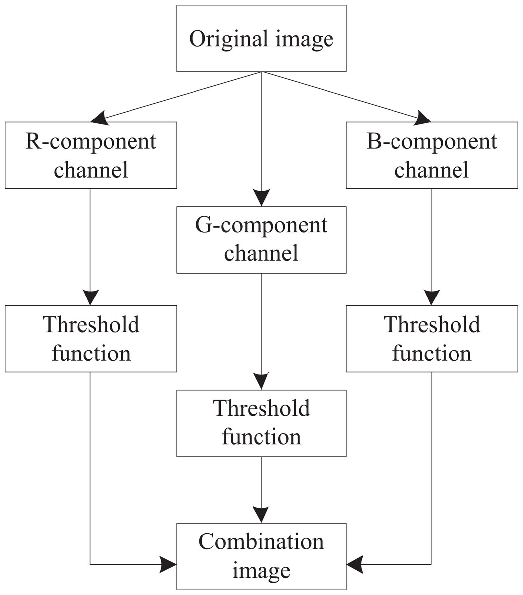
Figure 1: Improved framework for LoG operator.
Define the noisy image model as:
(1)
In the formula, represents the noisy image, represents the original image of size without noise, and represents Gaussian noise.
Decompose the noisy image into gray images of R, G, and B channels, perform edge detection on each channel using the LOG operator to obtain edge images, and then perform wavelet decomposition of the same scale on both the noisy and edge images to obtain two sets of wavelet coefficients and . Subtract the two sets of wavelet coefficients obtained to obtain the wavelet coefficient of the non-edge image. Afterwards, the wavelet coefficients of the edge image and the non-edge image were processed using different improved threshold functions, resulting in two new sets of wavelet coefficients and . Add the two newly obtained sets of wavelet coefficients together to obtain a set of wavelet coefficients for the denoised image. To reconstruct the images for the R, G, and B channels, the inverse wavelet transform is performed on the corresponding wavelet coefficients. Finally, the gray reconstructed images of the three channels are synthesized to obtain the denoised image .
Hard threshold function and soft threshold function are the most common threshold functions in wavelet threshold denoising (Al-Khafaji et al., 2022). Among them,
The hard threshold function is:
(2)
The soft threshold function is:
(3)
In the formula, represents the wavelet coefficients obtained from the noisy image after wavelet transform, represents the wavelet coefficients obtained after threshold processing, and represents the threshold.
Nevertheless, the threshold function described above may mistakenly suppress valuable image details as noise, thereby causing distortion in the reconstructed image. To address this issue, an improved algorithm is adopted to apply new threshold functions to both non-edge and edge parts:
① For non-edge parts of the image, improvements are made based on the soft threshold function. For wavelet coefficients greater than the threshold, the soft threshold function only calculates the difference between the wavelet coefficients and the threshold. While the method is effective in noise removal, it significantly distorts the wavelet coefficients associated with essential image details, resulting in the loss of information and noticeable blurring. Therefore, in improving the threshold function, a threshold error correction coefficient is added to the threshold, and the difference between it and the correction threshold is used for error correction to reduce distortion. Define the improved threshold function as:
(4)
In the formula, represents the threshold error correction coefficient, which is a constant of 0.5–1. For non-edge smooth parts, wavelet coefficients above the threshold are directly corrected, while wavelet coefficients below the threshold are directly set to 0.
② For the edge part of the image, simple error correction of wavelet coefficients cannot guarantee the clarity of the image contour. Therefore, we will continue to improve the threshold function. Because the high-frequency subgraph after wavelet transform contains most of the energy corresponding to the edges and contours of the image, it is necessary to consider the energy near the wavelet coefficients and compare its relationship with the correction threshold. If its energy is greater than the correction threshold, directly calculate the absolute value of the difference between the energy near the wavelet coefficient and the contraction threshold, then calculate the difference with 1, and multiply it with the wavelet coefficient to obtain a new wavelet coefficient; if the wavelet coefficient is less than the correction threshold, it is directly set to 0.
The improved threshold function is defined as follows:
(5)
In the formula, represents the degree of contraction of the wavelet coefficients, which is controlled by a constant of 0.5–1. represents the energy near the wavelet coefficients in various directions at the edge of the image, expressed as:
(6)
In addition, for the selection of the threshold , a universal threshold is chosen because under the normal Gaussian noise model, for the joint distribution of multidimensional independent normal variables, when the dimensionality tends to infinity, the probability of coefficients greater than this threshold containing noise signals tends to zero:
(7)
In the formula, and represents the number of pixels in the horizontal and vertical directions of the image; represents the standard noise variance.
Extracting image contours based on the LoG operator
As the most essential structural elements of an image, edges benefit significantly from denoising, which improves their clarity and definition (Atal, 2023). The so-called edge refers to the collection of pixels around it that exhibit a step-like or roof-like grayscale change. During the image acquisition process, noise is inevitably introduced due to random disturbances and external influences. The filtering of two-dimensional images aims to suppress noise, enhance image features, improve image quality, and provide a high-quality image with a high signal-to-noise ratio for subsequent processing (Kondo et al., 2022).
This study utilizes the Marr operator to first smooth the image and then perform edge detection to achieve the optimal filtering effect. The Marr operator uses a Gaussian function with a normal distribution as the smoothing function (Beram et al., 2022), that is:
(8)
Firstly, the Gaussian function is used to convolve the image , resulting in a smoothed image as follows:
(9)
In the formula, represents the two-dimensional convolution operation of two functions and .
(10)
In the formula, and represent two variables.
In the above process, the parameter in Eq. (8) represents the variance of a Gaussian distribution, which can be used as a smoothing factor. The larger the value of , the more high-frequency parts are restricted, which can suppress noise. However, the boundaries of the image become blurred. To obtain the Marr operator, the following Laplacian operator must also be used, namely:
(11)
In the formula, and represent the second-order partial derivatives of and .
As a second-order differential operator, the Laplacian is highly sensitive to image noise, making it challenging to differentiate between noise and true edges. Additionally, its lack of directional sensitivity limits its utility in precise boundary detection.
The second step is to use the Laplacian operator on the smoothed image and obtain the expression of the Marr operator based on the convolution properties:
(12)
In the formula:
(13)
is obtained by combining Eqs. (11) and (4), and is called the Gaussian Laplacian operator, abbreviated as the LoG operator. It is an axisymmetric operator, and its one-dimensional function graph is shown in Fig. 2.
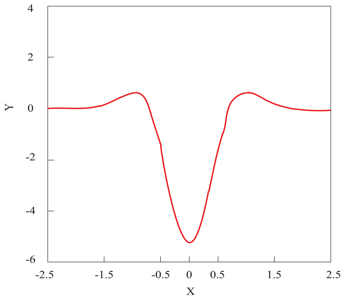
Figure 2: LoG operator one-dimensional function image.
The specific steps for using the LoG operator for image contour detection are:
-
(1)
Scan the image in raster order, and when 255 pixels without tracking markers are found, they are considered as the starting point of a boundary, with coordinates denoted as ;
-
(2)
Starting from the left adjacent 0 pixels of a pixel , eight neighboring pixels are arranged in counterclockwise order. If all eight neighborhoods have 0 pixels, they are isolated points. Otherwise, the initial 255 pixels encountered are denoted as ;
-
(3)
In the 8-neighborhood of , starting from the next pixel of , search for 255 pixels in a counterclockwise direction, and mark the first discovered 255 pixel as ;
-
(4)
When and , boundary tracking end. Otherwise, repeat step 3.
Until the search for all pixels in the image is completed, the image contour extraction is finished.
Multi-dimensional image contour matching based on the Fourier descriptor
After extracting the contour of the image using the LoG operator, Fourier descriptors are employed to determine contour matching points based on the image’s contour features.
Fourier descriptors are the Fourier transform coefficients of the shape boundary curve of an object (Jaskólski, Czaplinski & Tomczak, 2024). It is the result of the frequency domain analysis of object boundary curve signals. This method characterizes curves in a manner that is unaffected by shifts or rotations of the origin, ensuring geometric invariance. Take the horizontal axis of the image as the real axis and the vertical axis as the imaginary axis; that is, a point on the plane can correspond to a complex number. By starting at an arbitrary point on the closed boundary of a planar shape and traversing it once in a counterclockwise direction, a one-dimensional complex sequence of boundary points can be obtained:
(14)
In the formula, represents the imaginary number. The sequence satisfies the periodic boundary condition, and the sequence is:
(15)
In the formula, represents the digital frequency; represents the boundary complex sequence, and is the spectral coefficient of the boundary complex sequence . Among these, the high-frequency coefficients correspond to fine contour details, whereas the low-frequency components capture the overall shape of the contour. The DC component corresponds to the geometric center position of the area surrounded by the boundary, that is:
(16)
In the formula, the real and imaginary parts of the DC component are, respectively, the horizontal and vertical coordinates of the geometric center position of the area enclosed by the image boundary. The contour shape of the image boundary curve can be reconstructed by inverse Fourier transform using Fourier transform coefficients (Firsov, Khakhulin & Komkov, 2023), that is:
(17)
If only the first low-frequency coefficients of are taken, and the high-frequency coefficients are filled with zeros, can be approximately reconstructed through the inverse Fourier transform, and the approximate contour of the closed boundary can be obtained as follows:
(18)
As a result, the generated curve closely approximates the original image contour, although abrupt changes in the contour are typically smoothed out. The subset of Fourier coefficients in this sense is called a Fourier descriptor.
To identify shapes with rotational, translational, and scaling invariance, Fourier descriptors need to be normalized (Onural, 2024). According to the Fourier transform properties, by translating the starting point position of the shape boundary of an object, with a translation length of , enlarging the object by times, and rotating it by an angle of , the Fourier transform coefficients of the new shape are obtained as follows:
(19)
From formula, it can be seen that when using Fourier coefficients to describe shape, has rotation invariance and balance invariance, and is independent of the choice of curve starting point.
When an object is translated, only the value of in its component is changed. Dividing the amplitude of each coefficient (except ) by , remains invariant to scale changes and has rotation, translation, and scale invariance. It is independent of the starting point position of the curve and is used as a Fourier descriptor. Therefore, the normalized Fourier descriptor is defined as:
(20)
In the formula, represents modulus taking.
Considering each contour descriptor as a feature vector allows the similarity analysis of image contours to be reformulated as a problem in multidimensional feature space. Determine the similarity between the contours based on the Euclidean distance between them. The calculation method for the Euclidean distance is:
(21)
In the formula, and are Fourier descriptors of two contours. Consider the two contours with the closest Euclidean distance as contour pairs, calculate their centroids, and use them as the mapping point pairs for image registration in the following text.
Image registration based on projection transformation method
The image contours obtained through Fourier feature matching are used as mapping points, and image registration is completed through projection transformation method.
To achieve multidimensional image registration, it is necessary to find the transformation relationship between different images. Therefore, an improved projection transformation is used to complete the mapping of each image (Baum, Hu & Barratt, 2023). Projection transformation is mainly the process of projecting a certain plane onto another plane. Given that multidimensional image registration is intended for three-dimensional data, the approach adopted here involves mapping 2D projection transformations into a restricted form of 3D coordinate transformations (Yang et al., 2022). Consider the projection of points in 3D space onto image planes from different viewpoints, as illustrated in Fig. 3.
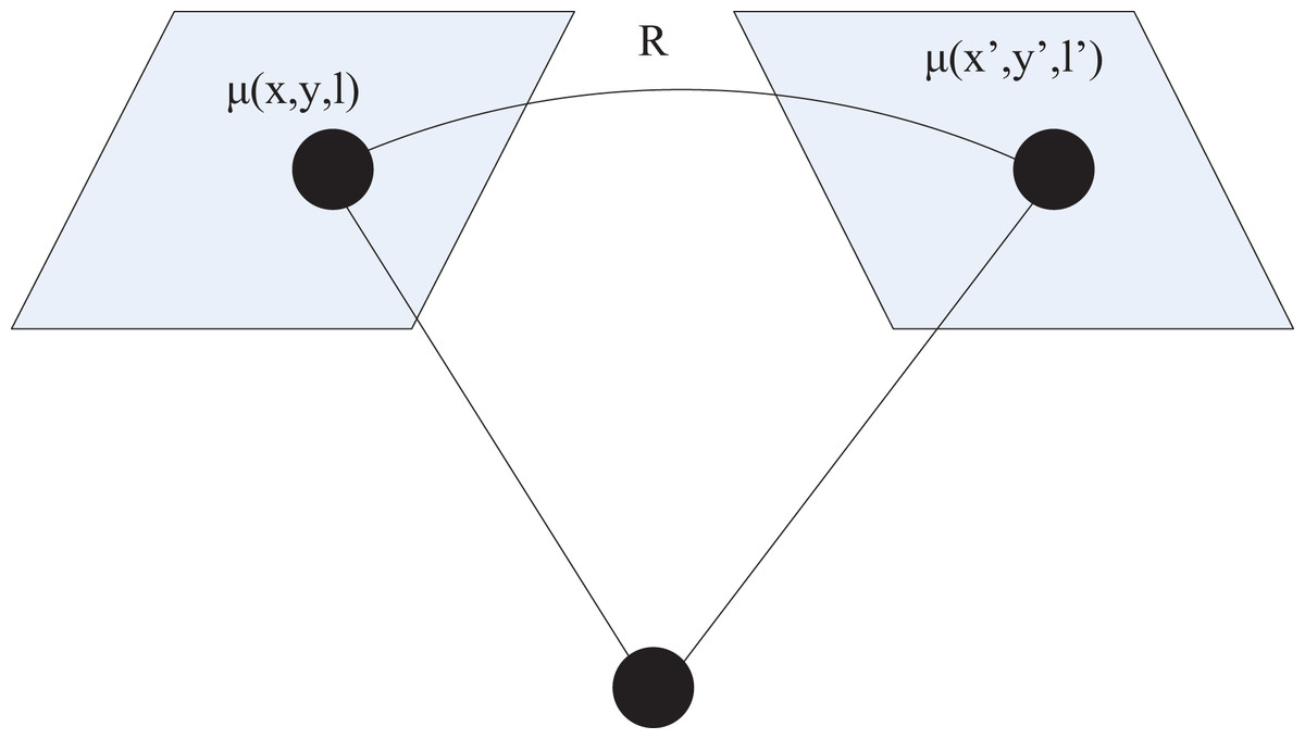
Figure 3: Schematic diagram of projection transformation.
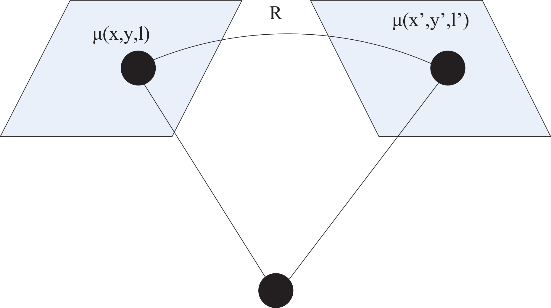
For a camera centered at the origin, point in 3D space, and its pixel coordinate is:
(22)
In the formula, is the camera parameter. Therefore, if represents the 3D coordinate point corresponding to pixel , then the coordinates of point can be represented as . The perspective projection relationship between two different image pixels and can be expressed as:
(23)
In the formula, represents the 3D rotation matrix.
Two-dimensional projection transformation is mainly related to homogeneous three-dimensional vector linear transformation. Under the condition of a homogeneous coordinate system, the non singular matrix of two-dimensional projection transformation is described as:
(24)
Rigid body transformation is a combination of rotation transformation, translation transformation, and scaling transformation. Affine transformation is a general transformation in rigid body transformation. Under homogeneous coordinate conditions, the matrices corresponding to the two transformations in 2D space can be represented as:
(25)
In the formula, represents the rotation angle during the rotation transformation process, represents the horizontal translation component of the translation transformation, and represents the vertical translation component. In general, affine transformation in Cartesian coordinate system can map pixel coordinate to pixel coordinate as follows:
(26)
The projection transformation can map to using the following formula:
(27)
After the mapping is completed, the registered image can be obtained.
Experiments and analysis
Experimental subjects
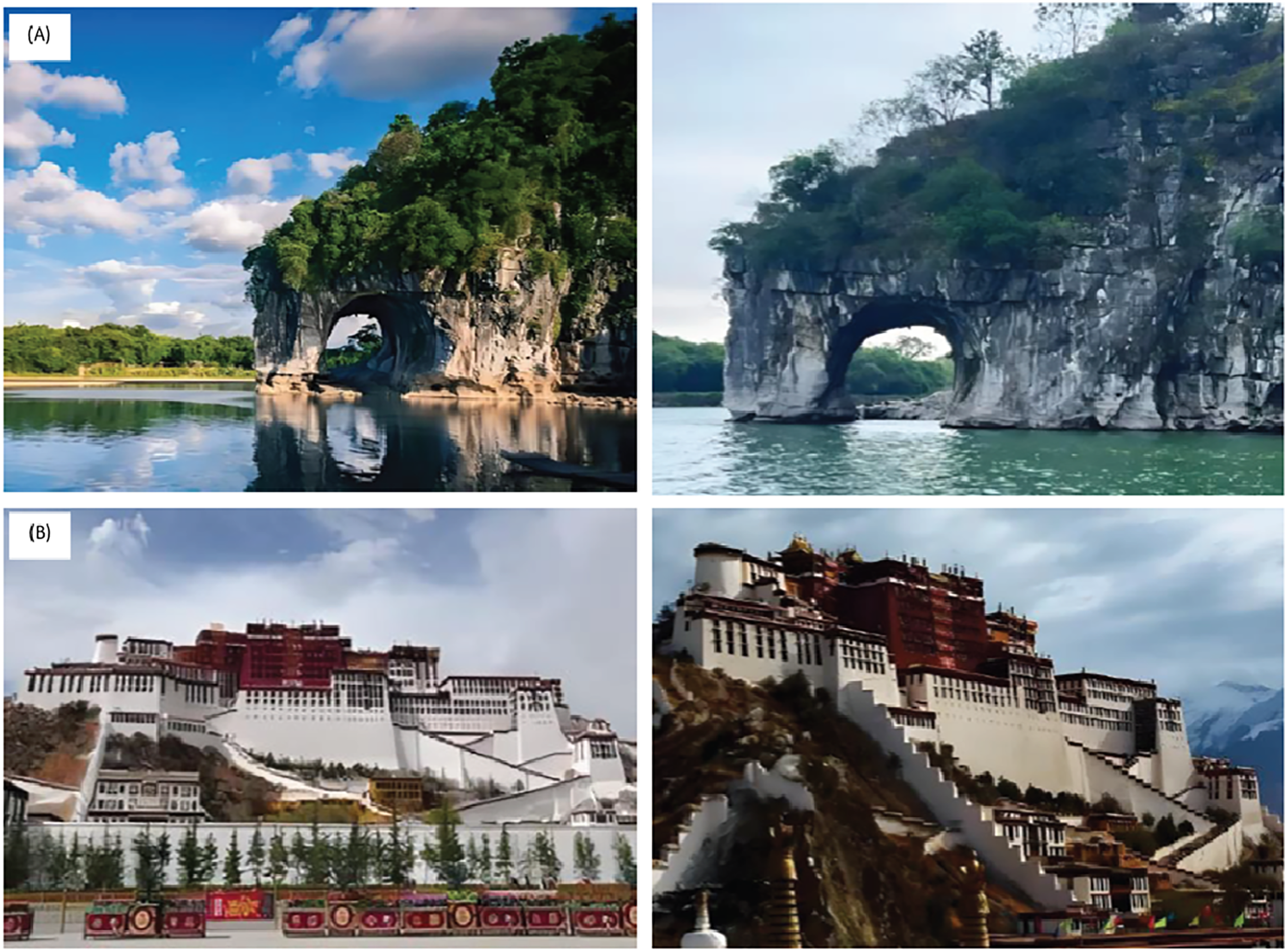
The experimental evaluation was conducted using two datasets: high-resolution landscape photographs of Elephant Trunk Hill and the Potala Palace, each at a resolution of 1,920 × 1,080 shown in Fig. 4. The images vary by capture angle and lighting conditions to simulate real-world projection discrepancies. These datasets were selected for their diverse edge structures and geometric richness, allowing robust testing of contour-based registration methods.
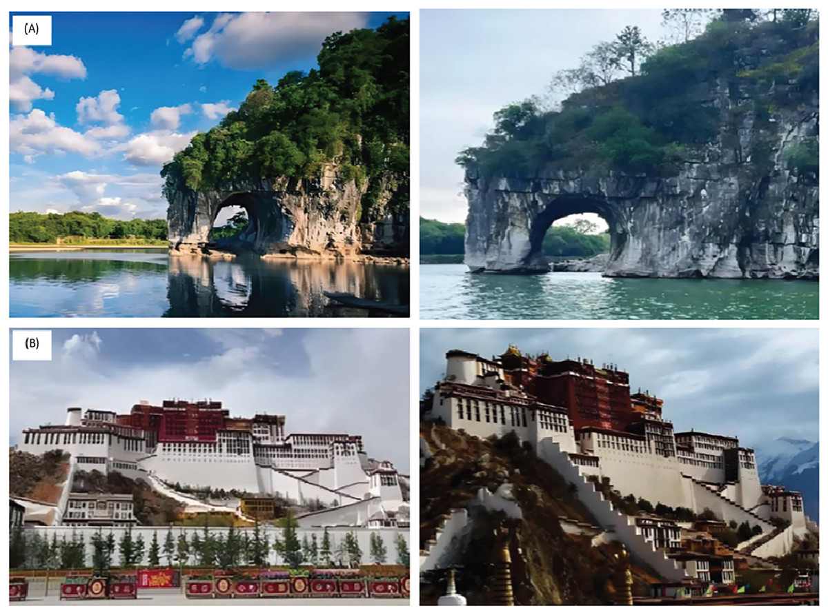
Figure 4: Images of (A) Elephant Trunk Hill and (B) The Potala Palace from different dimensions.
All experiments were conducted on a workstation equipped with an Intel Core i7 CPU, 16 GB of RAM, and without GPU acceleration. The average processing time per image pair was approximately 2.3 s, demonstrating near real-time performance even on standard hardware.
To verify the effectiveness of image registration, the root mean square error index was used for validation. The larger the root mean square error, the greater the distance between the reference image and the registered image, which means that the larger the value, the lower the registration accuracy. The mathematical expression for root mean square error is as follows:
(28)
In the formula, represents the coordinates of the feature points contained in the image to be registered; represents the coordinates of the feature points contained in the reference image; represents the transformation model.
Analysis of experimental data
We investigated the impact of key hyperparameters on registration quality. Experiments with different numbers of Fourier descriptors demonstrated that the first 40 low-frequency components are sufficient to capture the primary shape characteristics without introducing sensitivity to noise. For the wavelet threshold correction coefficient, values in the range [0.6–0.8] balanced edge retention with noise suppression. These findings informed our parameter settings. Scalability was assessed by registering image pairs of different resolutions (1,280 × 720 to 3,840 × 2,160). The method retained high accuracy (≥97.5%) across scales, and computation time increased linearly, suggesting good scalability. To determine component-wise contributions, we performed ablation tests by removing each module. Removing wavelet denoising resulted in a rise in RMSE to 0.47, underscoring its significance in maintaining edge integrity. Omitting Fourier normalization reduced rotation-invariant accuracy. Together, these results confirm that the LoG operator and Fourier descriptors are key to robustness and precision.
Figure 5 demonstrates that contour extraction using the LoG operator, combined with Fourier descriptor-based feature matching, resulted in precise and reliable matching performance. The corresponding feature points in the two images are accurately marked with red dots at similar positions, indicating a high degree of consistency in the matching positions. Especially in the hollowed-out part of the Xiangbi Mountain rocks, a relatively large number of contour pairs were matched, reflecting the rich similarity features of the area. These precisely matched contours provide a solid foundation for subsequent projection transformation image registration, ensuring a more accurate and reliable registration process. Therefore, the results in Fig. 5 not only validate the effectiveness of feature extraction and matching algorithms but also provide important guarantees for the successful implementation of the entire image registration process.
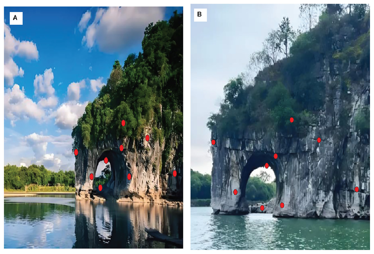
Figure 5: Matching effect of image contours.
(A) Reference image with selected contour points in red. (B) Target image captured at different time/angle, with corresponding contour in red.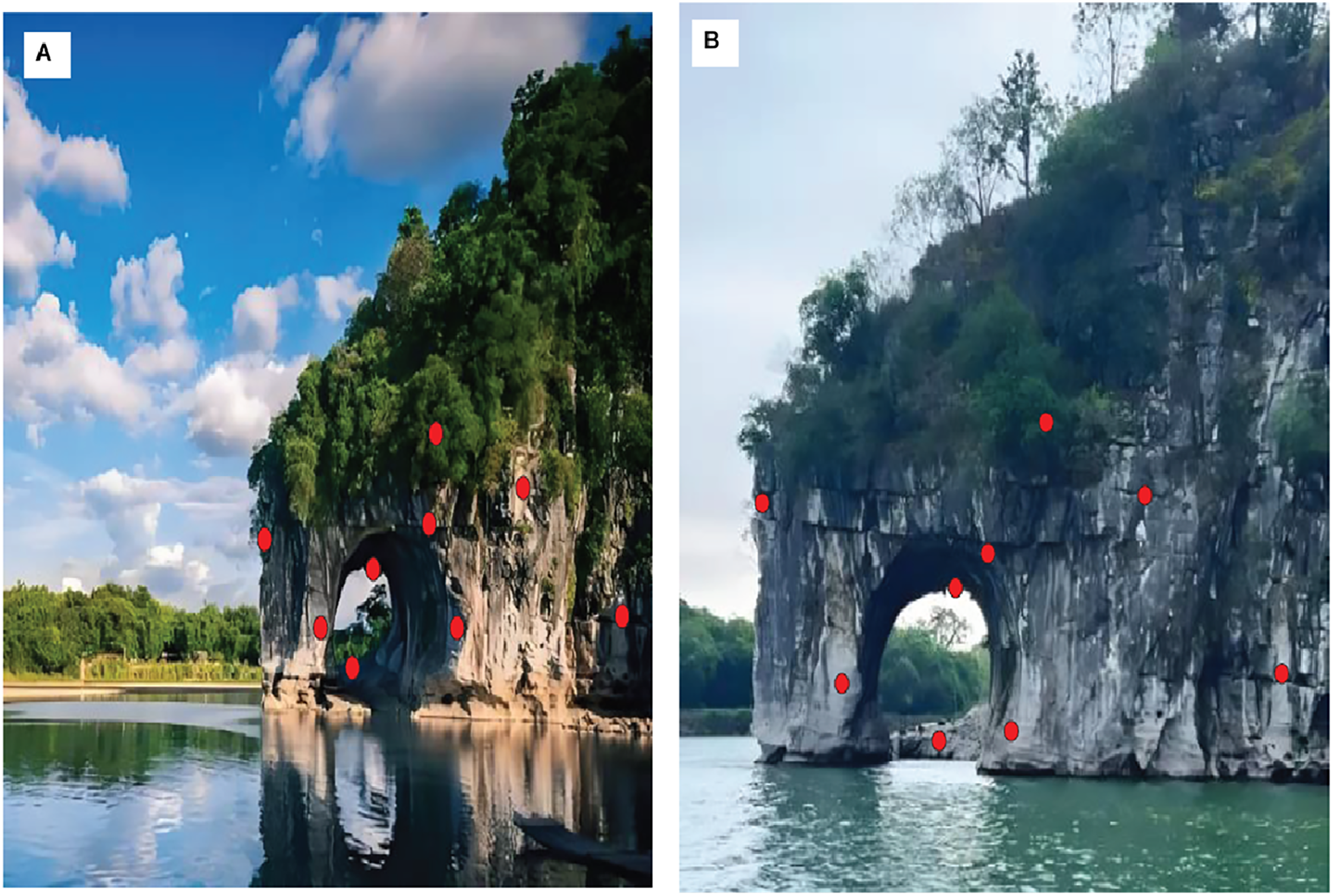
To verify the image registration effect of the method of this article, it was compared with four image registration methods of Arora, Mehta & Ahuja (2023), Mohammadi, Sedaghat & Rad (2022), Hjouj, Jouini & Al-Khaleel (2023), and Liaghat et al. (2023). The image registration results are presented in Fig. 6, while the corresponding root mean square error (RMSE) values are provided in Table 1.
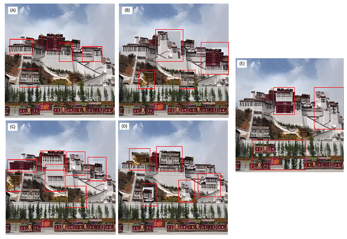
Figure 6: Image registration results using different methods.
(A) The registration results of this article’s method, (B) Registration results of Arora, Mehta & Ahuja (2023), (C) Registration results of Mohammadi, Sedaghat & Rad (2022) (D) Registration results of Hjouj, Jouini & Al-Khaleel (2023), (E) Registration results of Liaghat et al. (2023).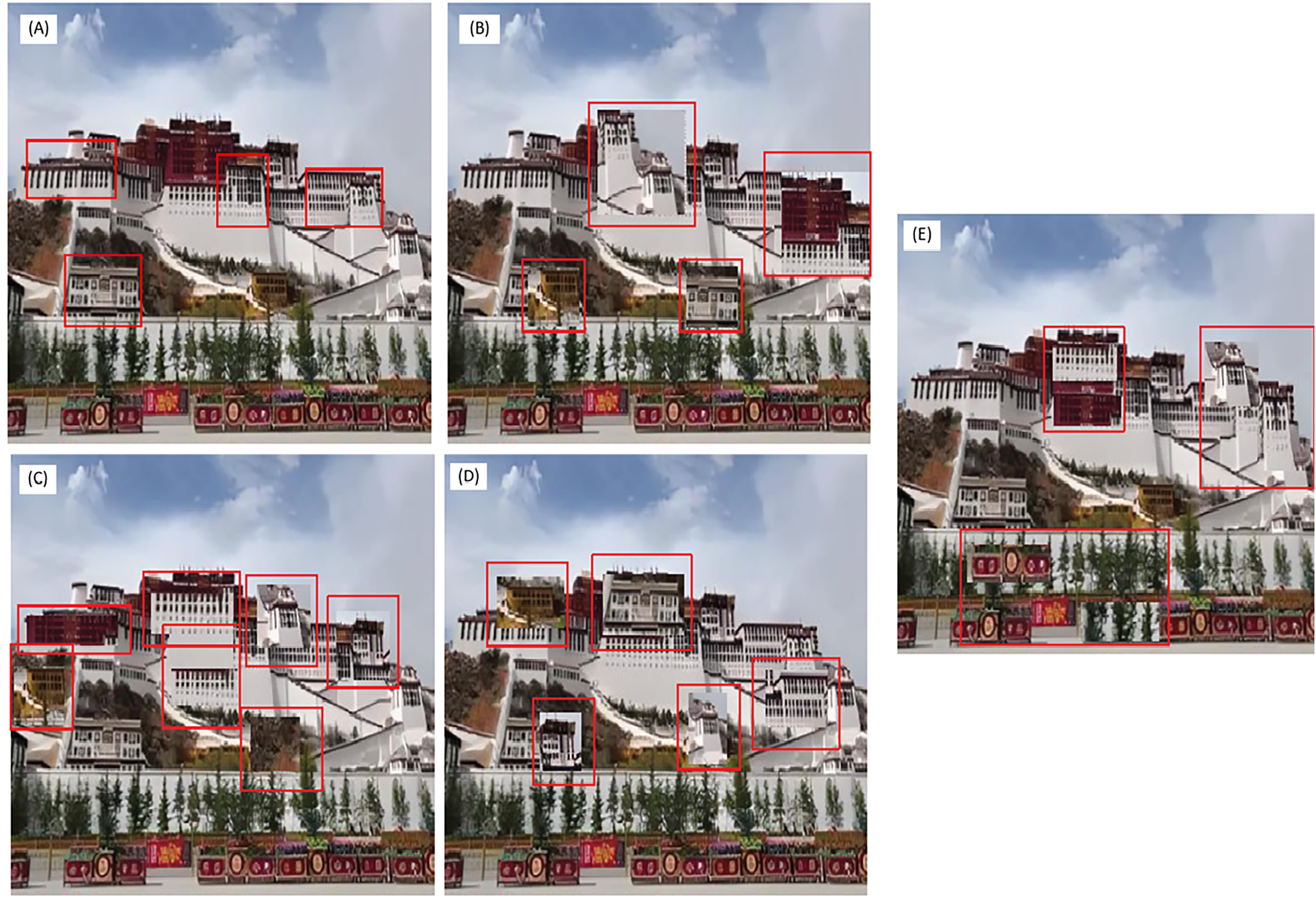
| Method | Registration time/s | Registration accuracy/% | Root mean square error |
|---|---|---|---|
| Method of this article | 0.41 | 99.1 | 0.31 |
| Method of Arora, Mehta & Ahuja (2023) | 0.53 | 94.1 | 0.42 |
| Method of Mohammadi, Sedaghat & Rad (2022) | 0.52 | 91.4 | 0.53 |
| Method of Hjouj, Jouini & Al-Khaleel (2023) | 0.48 | 93.8 | 0.46 |
| Method of Liaghat et al. (2023) | 0.50 | 94.3 | 0.41 |
From Fig. 6 and Table 1, it can be seen that when using multiple methods for image registration, the performance of the method of Mohammadi, Sedaghat & Rad (2022) is the worst, with the highest number of registration errors in the image registration results, and the largest root mean square error after registration is completed. Multiple results reflect the registration effect of the reference method (Mohammadi, Sedaghat & Rad, 2022). The registration results obtained by the methods of Arora, Mehta & Ahuja (2023), Hjouj, Jouini & Al-Khaleel (2023), and Liaghat et al. (2023) are relatively similar, with a registration rate of around 94% and a root mean square error of around 0.4. The method introduced in this article proves to be the most effective, attaining a registration accuracy of 99.1% and yielding a RMSE as low as 0.31. It can be considered a complete registration. The approach presented in this study demonstrates effective registration of multidimensional visual projection images, while preserving image integrity and ensuring high registration accuracy.
Conclusion
A robust and interpretable image registration framework tailored to multidimensional visual communication images is proposed in this study. The combination of wavelet-based denoising, the LoG operator for edge extraction, Fourier descriptors for contour matching, and affine transformation led to highly accurate registration with minimal RMSE. Our evaluation against four state-of-the-art methods showed improved performance across all benchmarks. The method is scalable to high-resolution datasets and demonstrates generalizability across varying image perspectives. It does not require training data, making it suitable for domains lacking labeled datasets. The method’s execution on standard CPU hardware—with processing times below three seconds per image pair—indicates its suitability for near real-time image registration tasks. Limitations include dependence on well-defined contours, which may be impacted in low-contrast or noisy conditions if preprocessing is omitted. Future work will focus on optimizing execution speed via GPU acceleration, exploring domain adaptation across different image modalities (e.g., SAR, medical), and integrating dynamic threshold selection to further improve robustness.
This article studies an intelligent registration method for multidimensional visual communication projection transformation images. By extracting image contours, matching contour pairs, and performing projection-based alignment, the proposed method achieves intelligent image registration, enabling spatial alignment of multi-angle and multidimensional images. Future improvements may focus on optimizing the contour pair matching process to increase its efficiency and output, supplying a greater number of matched pairs for projection-based alignment and ultimately enhancing the accuracy of image registration.