
Antifouling polymeric nanocomposite membrane based on interfacial polymerization of polyamide enhanced with green TiO2 nanoparticles for water desalination
- Published
- Accepted
- Received
- Academic Editor
- Lubna Rasheed
- Subject Areas
- Green Chemistry, Polymers, Biosynthesis, Natural Products
- Keywords
- Polymeric nanocomposite membrane, TiO2 nanoparticles, Antifouling, Interfacial polymerization, Polyamide
- Copyright
- © 2023 Abu-Dalo et al.
- Licence
- This is an open access article distributed under the terms of the Creative Commons Attribution License, which permits unrestricted use, distribution, reproduction and adaptation in any medium and for any purpose provided that it is properly attributed. For attribution, the original author(s), title, publication source (PeerJ Analytical Chemistry) and either DOI or URL of the article must be cited.
- Cite this article
- 2023. Antifouling polymeric nanocomposite membrane based on interfacial polymerization of polyamide enhanced with green TiO2 nanoparticles for water desalination. PeerJ Analytical Chemistry 5:e26 https://doi.org/10.7717/peerj-achem.26
Abstract
In the present investigation, the preparation and characterization of polyamide/TiO2 as thin film nanocomposites (TFN) for brackish water desalination was investigated. TiO2 nanoparticles (NPs) were synthesized by a green method using thyme plant extract as a reducing and capping agent. The TiO2 NPs was successfully prepared in pure crystalline anatase phase with 15 nm size, and −33.1 mV zeta potential. The antimicrobial tests confirmed the antimicrobial activity of TiO2 against gram-positive and gram-negative bacteria. In addition, TiO2 NPs showed a good photocatalytic activity in degradation of methylene blue dye. TFN based on interfacial polymerization was enhanced by embedding 5% of the greenly synthesized TiO2 NPs within the polyamide thin film active layer. The incorporation of TiO2 NPs was confirmed by SEM, atomic force microscope (AFM), surface wettability, and FTIR. Membranes performance was investigated based on flux, salt rejection and fouling resistance. The antifouling was examined using bovine serum albumin (BSA) as protein fouling by dead-end cell filtration system at 2 bar. The results showed the TFN increased in water flux by 40.9% and a slight decrease in NaCl rejection (6.3%) was observed, with enhancement in antifouling properties. The flux recovery rate of the modified TFN membranes after fouling with BSA solution was enhanced by 21.5% (from 61.7% for TFC to 83.2% for TFN). Also, they demonstrated remarkable anti-biofouling behavior against both bacterial strains.
Introduction
Water desalination is one of the most well-known methods in the world for meeting the growing demand for clean water, and it is superior to traditional methods that remove salts and minerals (Eveloy, Rodgers & Qiu, 2015). Desalination has been utilized since ancient times, and it has evolved to remove salts and dissolved minerals to the World Health Organization’s permissible limit of of potable water (500 ppm). Desalination plants number and size are widely spread and annually increased, their global output is expected to reach 192 million m3 per day by 2050 (Darre & Toor, 2018). In 2010 the increase rate was estimated to be 6.8% as an annual increase rate. From January 2019 to February 2020, 155 new desalination plants were installed worldwide and with an additional capacity of 5.2 million m3/day (Eke et al., 2020). Due to its ability to produce high-quality fresh water from a variety of water sources, such as seawater, and brackish water, reverse osmosis (RO) technology has been widely used for the sustainable supply of clean water by applying a reverse pressure greater than the osmotic pressure between the contaminated water and the freshwater (Huang et al., 2013). The semi-permeable RO membrane, which allows water to pass while rejecting other unwanted solutes, is essential to RO by membrane technology. Thin-film composite (TFC) membranes, which generally consist of an ultrathin active polyamide layer deposited on a porous polymer support membrane, currently dominate commercial RO membranes with a hierarchical structure (Zhang et al., 2020).
Interfacial polymerization has traditionally been used to establish Polyamide (PA) active layers of RO membranes for water desalination (salt rejection) by reaction at the top of porous substrates (usually polysulfone (PS) or PES) between two monomers, which are M-phenylenediamine (MPD) in aqueous solution and trimesoyl chloride (TMC) in organic solvents (Zhang et al., 2020). The formed layer typically has ridge and valley structures, which help to increase surface roughness and thus fouling tendency. However, PA membranes outperform cellulose acetate membranes in terms of permeability and salt rejection. Their fouling predilection is a stumbling block to more practical application. Furthermore, the development of efficient membranes to overcome the limitation of the trade-off between permeability and rejection remains the primary research focus (Song et al., 2016).
Preventing unwanted adsorption or adhesion patterns on the membrane’s surface is the goal of reducing polymeric membrane fouling. Several methods for reducing membrane fouling have been investigated. A hydrophilic modification of the membrane surface is one of these methods. There are several methods for hydrophilic adjustment of membrane surfaces. Within these methods, the incorporation of differing kinds of nanoparticles into membrane materials has received a lot of attention in recent years (El-Aassar, 2015).
The distinguishable physical and chemical characteristics of metal and metal oxide nanoparticles in comparison with their bulk particles have largely driven research into nanoparticle synthesis for a variety of applications. Titanium dioxide (TiO2) nanoparticles (NPs) have received a great deal of research interest in their importance in a variety of applications such as photocatalysis, oxygen sensors, and antimicrobial coatings. TiO2 NPs have a hydrophilic surface and are chemically and physically stable. TiO2 nanoparticles are encouraging nanomaterials for organic–inorganic hybrid TFC membranes due to these properties (Yang et al., 2011).
Madaeni & Ghaemi (2007) used TiO2 NPs to minimize fouling in polymer membranes by coating the surface to create a photocatalytic property and increase the hydrophilicity. Asadollahi et al. (2020) modified the polyamide membranes surface by coating it with varying concentrations of TiO2 NPs. When compared to pristine membrane, results showed an increase in hydrophilicity and significantly better fouling resistance.
Khorshidi et al. (2018) incorporate TiO2 NPs in a thin PA layer by the in-situ polymerization on commercial PES substrate surface to enhance the thermal stability and anti-biofouling. In the study, they used the biphasic solvothermal (BST) reaction for the NPs synthesis. The thermal stability and anti-biofouling properties of the resulting TFN membranes were improved.
Rajaeian et al. (2013) incorporated aminosilanized TiO2 nanoparticles with the TFN active layer, resulting in the development of a novel TFN nanofiltration membrane. They used a polyethersulfone (PES) barrier coating on a porous -Al2O3 ceramic hollow fiber membrane as a support. Water flux was increased compared to the pure polyamide membrane with negligible rejection loss.
Kwak, Kim & Kim (2001) used a self-assembly process to create hybrid reverse osmosis (RO) membranes composed of aromatic polyamide thin films on a commercial polysulfone support with TiO2 NPs, with the purpose of solving biofouling problems. First, TiO2 NPs were synthesized using a sol–gel process. They demonstrated improved RO performance, with increased water flux and biofouling resistance.
Moreover, Kim et al. (2016) prepared polyamide TFC membranes through interfacial polymerization (IP), with TiO2 NPs added both during and after the IP. Instead of an organic TMC solution, TiO2 NPs were synthesized and added to the aqueous MPD solution. TiO2 NPs greatly improved the hydrophilicity of the membranes, causing an increase in water flux. Furthermore, a BSA fouling test revealed that TiO2 NPs drastically enhance the antifouling properties of both membranes.
In comparison between the preparation methods of the support substrate, the spin coating and the traditional by-Kinfe casting, the spin coating process increased solvent evaporation and reduced preparation time as well as may be reduced the hand person error through casting according to Burmann et al. (2014). Jin et al. (2022) have used silver nanoparticles to modify the PA layers via in situ chemical reduction. For live Escherichia coli (E. coli) bacteria, the modified membrane has a high strong antibacterial rate (99.99%). Water permeability and salt rejection are almost completely unaffected by the Ag modification.
For the synthesis of different nanoparticles, green technology has been intensively considered. Such approaches would provide steric stabilization of nanoparticles against aggregation while eliminating the use of standard caustic and combustible reducing agents like sodium borohydride (Goutam et al., 2018). Thus, generating less hazardous waste that harms the environment (Hussain et al., 2016). TiO2 NPs was previously synthesized using flower and soybean extracts in a green synthesis process and used in photocatalytic waste treatment applications (Kashale et al., 2017). Plants such as pomegranate peel extract (Abu-Dalo et al., 2019a) and jatropha curcas L (Goutam et al., 2018) have recently been studied for synthesis of TiO2 NPs. According to previous research, TiO2 NPs synthesized using green approach showed effective antibacterial properties (Sahaya et al., 2014; Ahmad, Khatoon & Sardar, 2014). Jakson et al. (2021), have used of antibacterial properties on the layer of a commercial (TFC) membrane using (Pennisetum purpureum) leaves-derived cellulose nanocrystals (CNC). The results demonstrated strong bacterial toxicity, inactivating 89% of attached E. coli cells under contact. A copper NPs and poly (ethylene glycol)-modified thin-film composite polyamide membrane was created by Ngo et al. (2022). The membrane permeability of changed membranes raised up to 40%, and they at the same had better antifouling properties against the Escherichia coli bacteria. By attaching amine-functionalized nanodiamond (ND) particles, Karami et al. (2022) provide an effective and expandable technique to minimize the fouling of (TFC) membranes. Sodium alginate (SA) and bovine serum albumin (BSA) fouling tests revealed that the ND layer significantly reduced membrane fouling. After 180 min of filtering, the flow of the pure TFC membrane decreased by 42% (SA) and 21% (BSA), whereas the permeability of the ND-modified membrane prepared by adding 1000 ppm ND particles dropped only by 15% (SA) and 9% (BSA). The deactivation and death rate of Escherichia coli (E. coli) bacteria cells improved with the incorporation of ND particles. By adding chitosan-silver particles (CS-Ag) of various molecular weights, Armendáriz-Ontiveros et al. (2022) developed modified thin film composite (TFC) membranes and assessed their desalination and anti-biofouling properties. The results demonstrated a slight decrease in salt rejection and a 56% improvement in flux. additionally, stronger bactericidal activity.
The most damaging cause of the PA membrane is fouling, so the membrane must be developed while maintaining the selectivity and permeability trade-off by incorporating environmentally friendly nanoparticles. Therefore, developing membranes with anti-fouling/anti-biofouling performance is very significant for the practical application of the membrane. TiO2 is among the distinctive nanoparticles that have been used as polymer functionalizing agents, TiO2 NPs have been studied extensively in polymeric membranes due to their chemical stability and antimicrobial properties. green synthesis using plant extract as a reducing and stabilizing agent has been proven to be very effective in the synthesis of a variety of nano-scaled particles including TiO2 NPs (Hussain et al., 2016). A green process is a clean approach, simple, reliable, and eco-friendly in which hazardous byproduct is minimized due to the use of less toxic materials (Arabi et al., 2020). Many studies have also been conducted to explain TiO2 nanoparticles’ effective antibacterial activity when compared to chemically synthesized TiO2. But to the best of our knowledge, no investigation was found for the impetrated TiO2 Nps within the TFN matrix for water desalination purposes.
In this study PES membrane was used as a support for TFC and TFN polyamide membrane. The PES support membrane was prepared using a spin coater instead of using the traditional casting method with a knife. The greenly prepared TiO2 NPs were added to the PA active layer to improve the membrane’s hydrophilicity and organic antifouling performance. FTIR spectroscopy, scanning electron microscope (SEM), Atomic Force Microscope (AFM), and surface wettability were used to characterize both TFC/TFN membranes. The separation performance of the membranes was also evaluated and compared. The antifouling was examined using bovine serum albumin (BSA) by dead-end cell filtration unit at 2 bar. Thin film nanocomposite membranes were tested for antimicrobial properties using gram-positive and gram-negative bacteria.
Materials & Methods
Materials
Titanium tetra-isopropoxide (C12H28O4Ti) was used as a starting material (Sigma Aldrich, Co. LLC, Germany). Aqueous plant extract of Thyme plant from Wadi Hassn, which grows abundantly in mountainous areas of Jordan was used as a capping and reducing agent (Ahmadi & Jafarizadeh-Malmiri, 2021) in TiO2 NPs synthesis. According to a previous study in Jordan for the same location, the thyme was of Thymus bovei, with a preferable aromatic flavor and odor (Kherissat & Al-Esawi, 2019). Thyme and its constituents contain phenolic compounds such as thymol and carvacrol, which are naturally antimicrobial and antioxidant sources used in veterinary medicine, agriculture, food, and medicine. The polyethersulfone (PES) granule (Mw 58,000 g/mol, Goodfellow, England), polyvinylpyrrolidone (PVP) (Mw 58,000 g/mol, Acros Organics, Germany) as pore former and 1-methyl-2-pyrrolidinone (NMP) (Thermo, ACROS, USA) were used to fabricate the PES substrate. Methylene blue (MB; Sigma-Aldrich, Inc., St. Louis, MO, USA). Sodium Chloride (NaCl), Magnesium Chloride (MgCl2), and Calcium Chloride (CaCl2) were from (Sigma Aldrich, Darmstadt, Germany). M-phenylendiamin (MPD), Trimesoyl Chloride (TMC) from Sigma Aldrich (St. Louis, MO, USA). n-hexane 96% (Sigma Aldrich, Darmstadt, Germany) were used for PA thin film preparation. Bovine serum albumin (BSA) from Sigma Aldrich (St. Louis, MO, USA) was used as a foulant in the antifouling test.
Nutrient agar, meat extract, peptone, casein peptone, and soybean peptones were purchased from Liofilchem (Roseto, Italy); nutrient broth (Oxoid, Mumbai, India), Sodium chloride (extra pure, Lobachemie, Mumbai, India), D-glucose (JHD, Guangdong, China), lecithin, and di-kaliumhydrogenphosphate from Riedel de- HaenAG Seelze-Hannover, Germany; tryptone soya agar (casein soya bean digest medium) (Oxoid, Hampshire, UK); Tween 80 (Polysorbate-80; ICI, London, UK); yeast extract agar (Mast Group, Merseyside, UK); agar (Merck, Branchburg, NJ, USA); and tryptone powder (Bio Basic, Markham, ON, Canada). Furthermore, Gram-negative Escherichia coli (E. coli) and Gram-positive Staphylococcus aureus (S. aureus) bacteria ATCC no. 8739 and 25913, respectively, were used.
Preparation of thyme plant extract
The thyme plants were washed several times with deionized water before air dried in a clean environment for three days. The dried plant was ground into a fine powder using a blender. To obtain a small size free of impurities, a sieve with a mesh number of 20 µm was used. 3g of the powder was boiled in 100 mL of deionized water for 30 min using the method described by Arabi et al. (2020). The resulting mixture was then filtered with Whatman filter paper, and the extracted extracts were kept in the refrigerator at 4 °C to preserve, avoid putrefaction and maintain the active ingredient properties for future use.
Synthesis of TiO2 NPs
The titanium tetra-isopropoxide (C12H28O4Ti) was used as a precursor for titanium. A mixture of 77% (v/v) deionized water and 7.7% (v/v) of the precursor, and 15% (v/v) aqueous extract, was added dropwise to a total volume of 100 ml. The solution was stirred in reflux at 50 °C for 4 h. The produced solution was centrifuged at 5500 rpm for 20 min. The product was dried for one hour at 60 °C. The final product has been calcined for 3 h at 500 °C to obtain the anatase crystal type, which has the highest photocatalytic and antimicrobial activity among the crystal structures as mentioned by Ripolles-Avila et al. (2019).
Preparation of substrate and thin film nanocomposite
The casting solution contained 18% of PES, 1% of PVP and 81% of NMP as a solvent at 60 °C with stirring for 24 h and then gas bubbles were removed by desiccator. Two steps in a Spin-Coater were used to deposit the casting solution on the glass plate, with a spinning speed of 200 rpm for 10 s and then 1500 rpm for 20 s, followed by the phase inversion method of immersing the glass plate in DI water.
TFC and TFN membranes were achieved through interfacial polymerization (IP) on fabricated PES membranes as support. Interfacial polymerization is a kind of growth polymerization where such polymerization takes place at the interface of two immiscible phases (usually two liquids), leading to a polymer that is transformed on the interface. To begin the IP process, the PES membrane was placed in a frame and allowed to contact with an aqueous solution containing MPD (2 wt/v%). After 2 min of retention on the PES membrane surface, the aqueous solution was discarded. The same membrane surface was then in contact with a pouring of 0.2 wt/v% TMC in an n-hexane solution to react with the previous monomer MPD for 1 min, then the organic solution was removed. The composite material membrane has been cured at 60 °C for 5 min until stored in RO water for further use. The whole membrane refers to the thin film composite (TFC) membrane. The fabrication for thin-film nanocomposite (TFN) membranes was the same as for TFC membranes, except for introducing 5% TiO2 nanoparticles into the aqueous solution using an ultrasonic bath.
Analysis of the synthesized TiO2 nanoparticles and the fabricated membranes
Ultraviolet–visible spectroscopy (UV–VIS) (Double beam UV-2450; Shimadzu, Kyoto, Japan) measurements were used to analyze the sample optical characteristics for the TiO2 NPs, Fourier-transform Infrared Spectroscopy (FTIR) (Bruker-Avance III, Billerica, USA) was used for functional group characterization.
For the crystalline phases, Crystallinity and average crystalline size, the synthesized TiO2 were evaluated using X-ray Diffraction (XRD) (Rigaku Ultima IV, Rigaku company, Tokyo, Japan). In addition, Debye Scherer relationship was used to calculate the average crystallite diameters (D) as follows: (1)
where k is the 0.9 crystal shape factor, λ is the X-ray diffraction wavelength of 0.15406 nm depending on the X-ray source, ß is the peak width at half maximum height, and Θ is the Bragg diffraction angle.
Analyzing elemental composition was done using X-ray fluorescence (XRF) (+NEXQC; Rigaku, The Woodlands, TX, USA). The surface hydrophilicity of the blend membranes was evaluated by a drop shape analyzer using a contact angle goniometer (Attension Theta lit; Biolin Scientific, Stockholm, Sweden). A scanning electron microscope (SEM) was used to examine the surface morphology of the nanoparticles and the membranes (Quanta FEG 450, Netherland), in addition to atomic force microscopy (AFM) for topography of membrane and roughness. dynamic light scattering (DLS; Theta Lite, USA) was used for the size distribution and stability of the nanoparticles. Thermogravimetric analysis (TGA) (Netzsch TG 209 F1 Iris) was used to confirm the purity of TiO2NPs prepared by green approach and to investigate the effects of membranes modification on their decomposition behavior, and the percentage of TiO2NPs within TFN membranes. The analysis was done at a heating rate of 10 °C/min from room temperature to 800 °C.
The catalytic performance of TiO2 nanoparticles was investigated using the Methylene blue (MB) dye as a model pollutant and was used for the photocatalytic treatment of polluted water and wastewater under the source of UV light source at 365 nm (UVP C-70G chromate-Vue Cabinet, Ultraviolet Sources: 254 nm UV of 1290 µW/cm2 and 365 nm UV of 2100 µW/cm2), and under sunlight simulator (Peccell’s sunlight simulator; PEC-L15, Peccell Technologies, Inc., Yokohama, Japan) with a sunlight irradiance of 100 mW/cm2. Antimicrobial efficiency was tested also against gram positive and gram-negative bacteria.
Membrane performance
Membrane filtration performance was tested in a dead-end filtration system (HP4750; Sterlitech, Auburn, WA, USA) with a 14.6 cm2 effective area. At first, the membrane was cut and placed into the cell according to its size. The membrane was then compressed for 30 min at 2.5 bars with deionized water.
The permeation flow (J0) is calculated at 2 bars using the equation: (2)
where W is the weight of the permeated solution in gram, A is the membrane surface area (m2), and ΔT is the duration of the experiment (hour). All calculations were repeated three times, and the average results were reported.
The feed solutions utilized to evaluate the membrane’s performance were 1000 ppm NaCl, MgCl2, and CaCl2 aqueous solutions and 2000 ppm NaCl to compare between the TFC and TFN that simulate brackish water composition. The tests were carried out at a pressure of 2 bar and a temperature of 25 °C. The concentration of the feed solutions and the concentration of the permeate were used to determine the solute rejection. The following equation was used to determine the rejection: (3)
where CF and CP are the feed solution and permeate concentrations, respectively.
Fouling resistance
The membrane’s antifouling properties were assessed utilizing conventional BSA as foulant. Model foulants for the TFC and TFN were 0.5g/L BSA. The permeated flux was measured before, and after adding foulant over time. The flux of solution with BSA foulant (J0) (kg/m2 h) was calculated at 2 bars and for 90 min. The membranes were cleaned with deionized water after filtering the BSA solution. After rinsing the membranes, they were submerged in deionized water for 20 min. After that, the water flux of cleaned membranes (Jw) was calculated. The following formula was used to determine the flux recovery (FR) (Wang et al., 2019): (4)
where the J0 is water flux before fouling, Jw is the water flux after fouling. The Eq. (5) was used to calculate the total fouling ratio (Rt): (5)
where the Jp is the flux with fouling. The following Eqs. (6) and (7) were used to define and determine percent of reversible fouling (Rr) and irreversible fouling (Rir). (6) (7)
Antimicrobial activity
The antimicrobial property of NPs was investigated using the liquid medium method against various pathogens bacteria including E. coli, and Staphylococcus aureus. (S. aureus) the pathogens cells tested were prepared from a (0.5) McFarland turbidity standard (5 × 10⁷ cell mL 1). The testing was incubated at 37 °C for 24 h according to Khashan et al. (2021).
The bacteria’s inhabitation rate was investigated by inoculating the broth with 0.2 mL of bacterial strains after the addition of TiO2NPs at various doses of 100, 500, and 1000 ppm. The optical density (O.D.) of the bacteria at a wavelength of 600 nm was used to estimate its growth, while the inhibition ratios were calculated using Eq. (8). (8)
where the control O.D is a result from bacteria without NPs and tested O.D is bacteria with nanoparticles
The antimicrobial activity of the membranes was assessed using the standard “ISO 22196:2007 Plastics—Measurement of antibacterial activity on plastics surfaces” as described in our paper previously (Alnairat et al., 2021).
Briefly, 13.0 g of nutrient broth in 1.0 L of DW was used. 28.0 g of nutrient agar was mixed with 1.0 L of DW to make Plate Count agar. Lecithin and polyoxyethylene sorbitan monooleate was used to prepare Soybean Casein Digest Broth (SCDLP broth).
Phosphate-buffered physiological saline was prepared by dissolving 8.5 g of NaCl in 1.0 L of DW and diluting 800 times. Autoclaving was used to sterilize all the media. Three TFN samples were compared to sex specimens of TFC membranes with dimensions of (2.2 × 2.2) cm2.
Half of the TFC was washed with 10.0 mL of SCDLP buffer. A dilution of 100 L was taken and cultured on plate agar. The remaining pieces were washed with SCDLP, diluted, cultured, and incubated in the same way.
The number of colonies from each dilution was counted after incubation. The following equation was used to calculate the number of viable bacteria found: (9)
where N is the number of viable bacteria recovered per cm2 of the tested membrane samples. C: plate count average for duplicate or triplicate plates D: the counted plate dilution factor V: the volume of SCDLP added to the samples (mL). When no colonies are recovered in any of the agar plates for a dilution series, the colonies are counted as “V” (where V is the amount of SCDLP added to the membrane in milliliters). The sterilization ratio was calculated using the following (Eq. (10)): (10)
where R denotes the sterilization ratio. A: the number of viable bacteria recovered per cm2 of the TFC membrane. B: the number of viable bacteria recovered per cm2 of the treated TFN membrane.
Results and Discussion
The results and discussion section is arranged in two parts. The results and discussion related to the preparation and characterization of TiO2 NP are summarized first, while the second part, summarized the features and performance of TFC and TFN.
Titanium oxide nanoparticles
Ultraviolet–visible spectroscopy (UV–VIS)
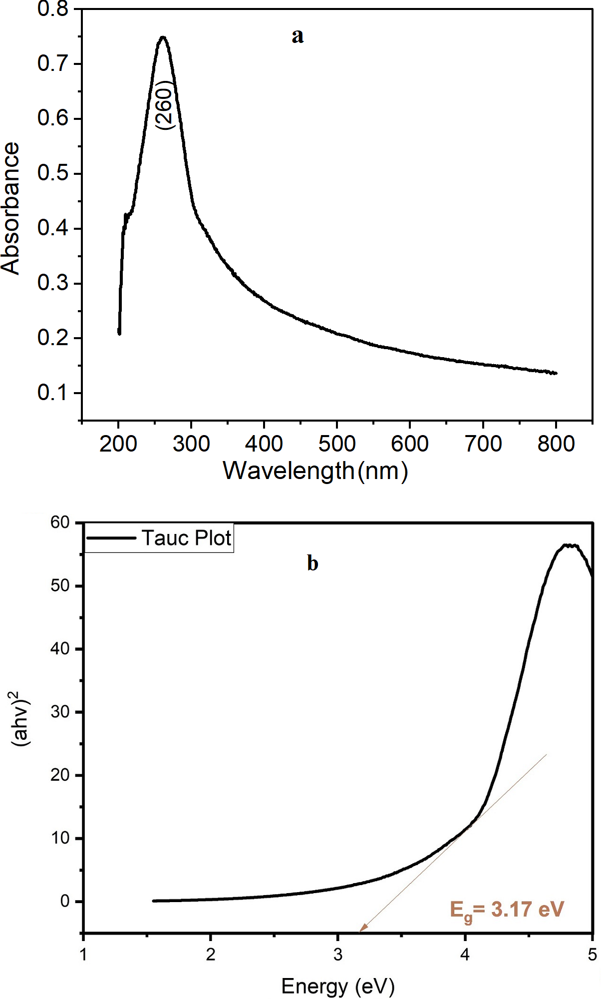
The absorption spectra of TiO2 NPs were analyzed to further investigate the optical properties and confirm the formation of TiO2 NPs. Figure 1A shows the absorption spectra of TiO2 NPs, which displayed strong and prominent absorption peak at 260 nm. This indicates that the TiO2 nanoparticle suspension has a high absorption capacity for ultraviolet light as reported by Gouda & Aljaafari (2012). The band gap energy of a TiO2 NPs describes the amount of energy required to excite an electron from the valence band to the conduction band. An accurate determination of the band gap energy is critical in predicting the optical properties. In 1966, Tauc proposed using optical absorption spectra to calculate the band gap energy. The Tauc technique assumes that the energy-dependent absorption coefficient can be represented by the following (Eq. (11)) (Makuła, Pacia & Macyk, 2018). (11)
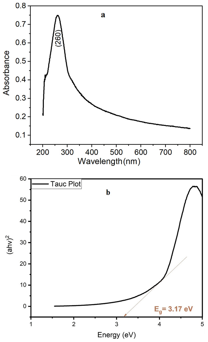
Figure 1: Spectrum results of green TiO2 NPs (A) UV–VIS absorption spectrum with (B) Tauc plot.
where h denotes the Planck constant, v: the frequency of a photon, Eg: the band gap energy, α: absorption coefficient equals 2.302 * absorbance, and B: a constant equal to 1240. The γ factor varies according to the nature of the electron transition and is equal to 1/2 for indirect transition band gaps and the result is shown in Fig. 1B. The energy band gap equals 3.17 eV confirm TiO2 NPs formation, the literature value for anatase is estimated to be between 3.10 and 3.20 eV (López & Gómez, 2012).
Fourier-transform infrared spectroscopy (FTIR)
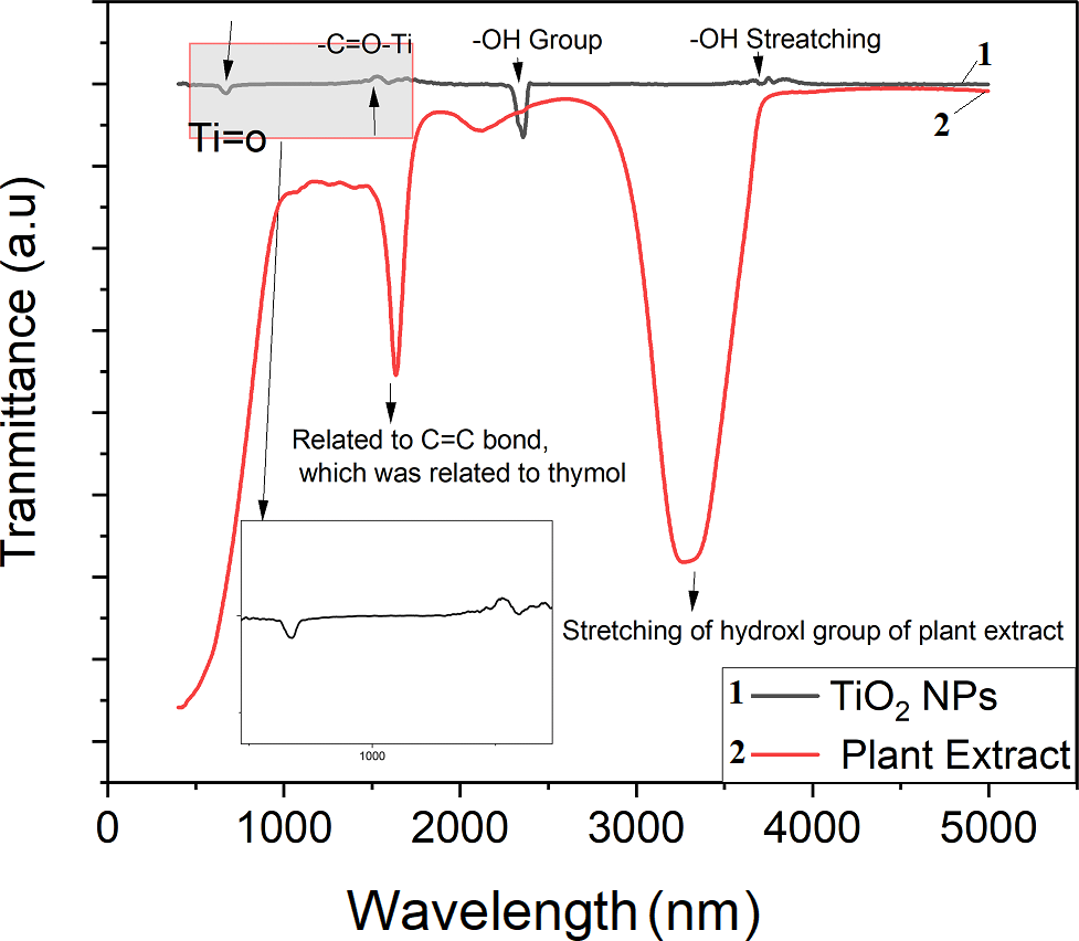
Figure 2 illustrates the FTIR spectra of the synthesized TiO2 NPs and the plant extract. Ti–O stretching and Ti–O–Ti bridging stretching modes correspond to an absorption peak between 500 and 700 cm−1 as reported by Goutam et al. (2018). The Ti-O-Ti bond is responsible for the observed peaks at 665 cm−1 and the peak appeared in the range of 1600–1700 cm−1 are ascribed to the -C =O-Ti bond from the residual of plant, and the amount of anatase infiltrative cavities may boost the number of hydroxyl groups that convert to hydroxyl radicals, increasing the rate of attack on organic compounds. FTIR spectra of the plant extract at 1640 cm−1 is related to the C = C which is related to the thymol and the stretching of H-bonded O-H groups in hydration water causes the absorption band at 3300 cm−1 (Ahmadi & Jafarizadeh-Malmiri, 2021).
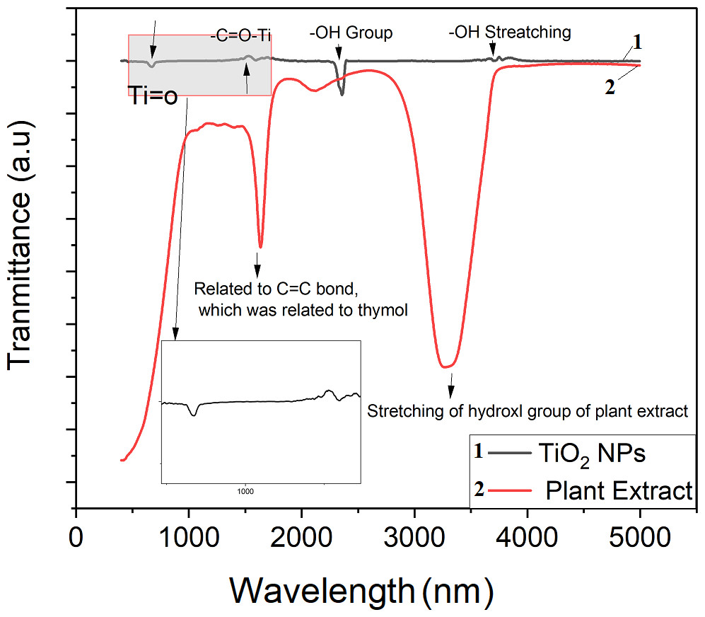
Figure 2: FTIR spectrum for plant extract and green TiO2 NPs.
X-ray diffraction (XRD) and X-ray fluorescence (XRF)
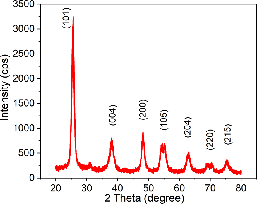
Figure 3 represents the synthesized TiO2 NPs XRD patterns, which show sharp peaks at 25.53°, 38.1°, 48.23°, 54.15°, 62.94°, 68.28°, and 75.44°, which correspond to the anatase phase’s (1 0 1), (0 0 4), (2 0 0), (1 0 5),(2 0 4), (2 2 0), and (2 1 5) planes, respectively (JCPDS No. 01-071-1166) (32). The average crystallite size was calculated using Scherrer equation (Kashale et al., 2017) to be around 8 nm, with sharp peaks indicating a strong crystallinity of 92.15%.
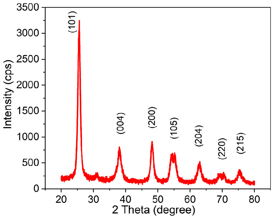
Figure 3: XRD spectra of the greenly synthesized TiO2 NPs.
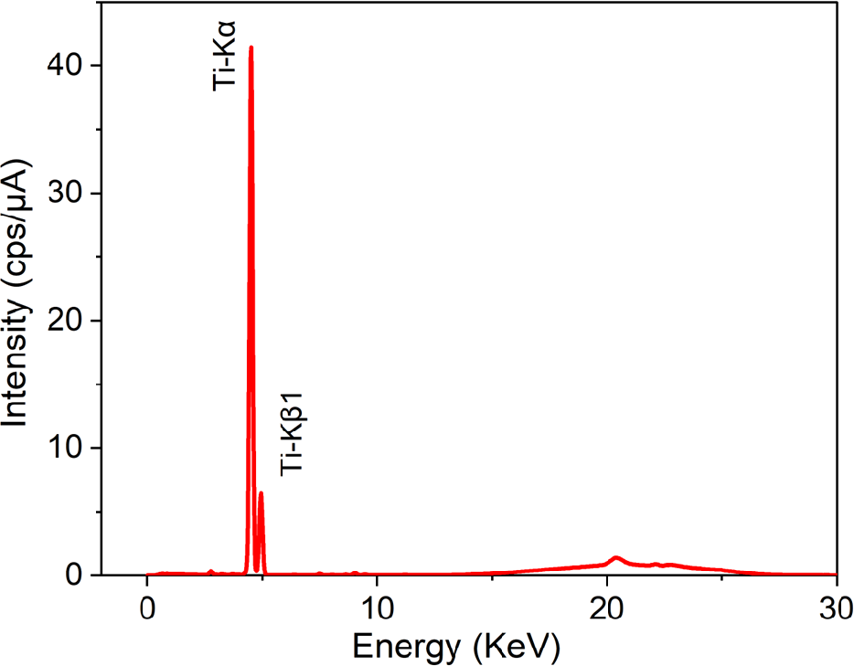
Figure 4 shows the energy dispersive X-ray fluorescence (EDXRF) spectra for the prepared TFC, TFN membranes and green TiO2 NPs. The results of nanoparticles spectra indicated the presence of Ti elements with Ti-K α and Ti-K β signals (4.51 keV and 4.93 keV, respectively) and showed a high concentration of Ti. Our results agree well with the results published by Archana et al. (2010) and Murali et al. (2016).
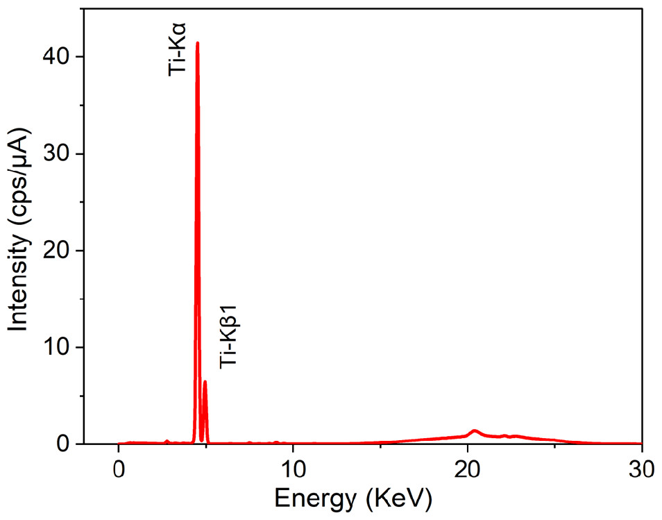
Figure 4: EDXRF spectra of greenly synthesized TiO2 NPs.
Scanning electron microscope (SEM)
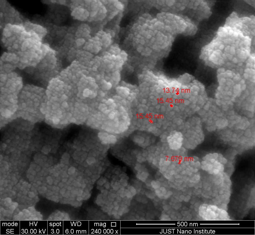
Figure 5 depicts SEM image for the prepared TiO2 NPs. The result showed a spherical form of the nanoparticles with a size distribution ranging from 7 to 5 nm. Also, SEM images indicated the presence of irregular and aggregated particles in range of 100 nm.
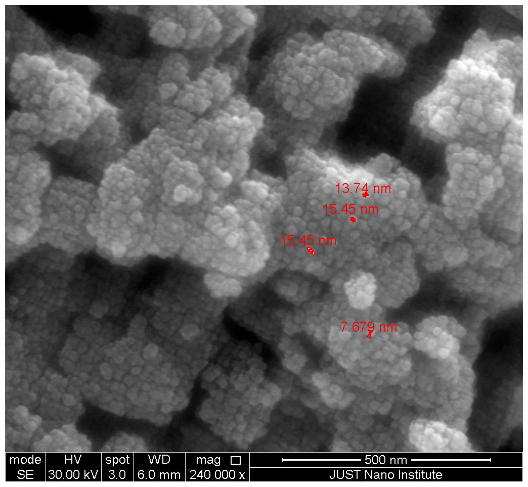
Figure 5: SEM image of the greenly synthesized TiO2 NPs.
Dynamic light scattering (DLS)
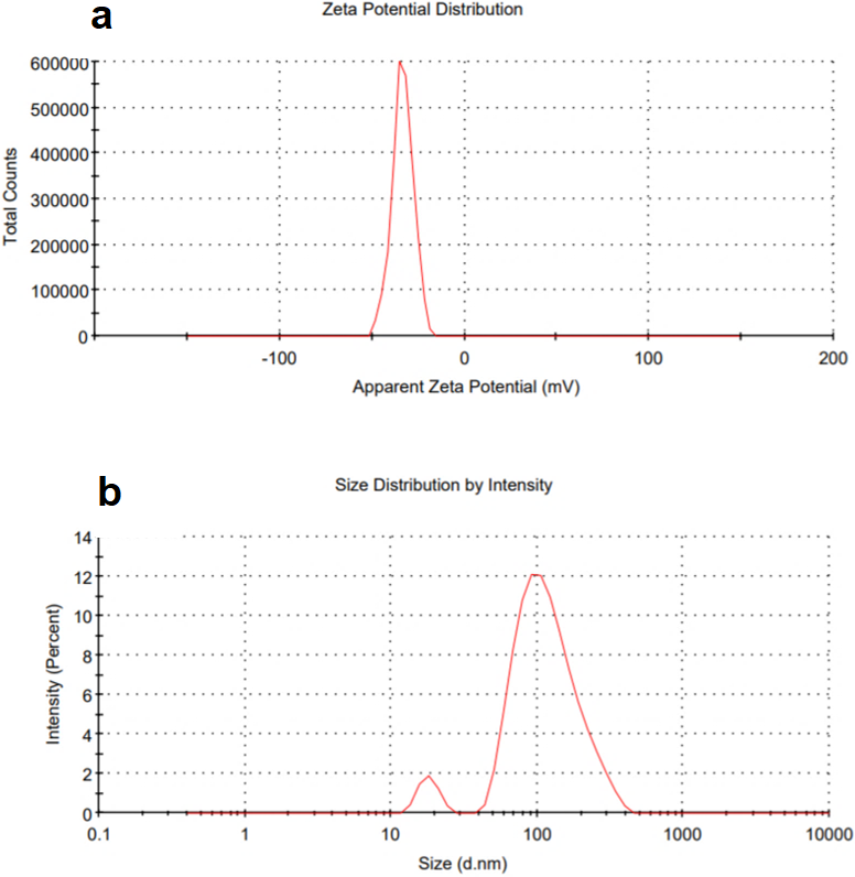
Surface charges of the TiO2 NPs in DI water and size distribution are shown in Fig. 6. A high positive or negative zeta potential causes flocculation and agglomeration resistance. If the zeta potential values of the particles are low, there is no strength to keep them from colliding and flocculating (Alnairat et al., 2021). Zeta potential (ζ) values of around ±30 mV in TiO2 NPs indicate that either negatively or positively charged colloidal particles have reasonable dispersion stability (Ceballos-Chuc et al., 2022). A negative zeta potential value of −33.1 mV was observed in Fig. 6A, which represents the strength of electrostatic repulsion in dispersion between charged particles and solvent. A high zeta potential represents good stability to molecules and particles of sufficient size that the solution or dispersion will resist aggregation and close to 35 mV finding (Ceballos-Chuc et al., 2022). Figure 6B shows peak at 18 nm, which is close to SEM image results and peak at 100 nm, also in consistence with the irregular aggregation shown in the SEM. It is well known that DLS measures the hydrodynamic radius and that a small number of larger particles (which could be aggregates or impurities) usually have a larger population of smaller particles. The polydispersity index (PDI) was 0.3 signifies a homogeneous population while implying a uniform sample in terms of particle size and suitable for the DLS test.
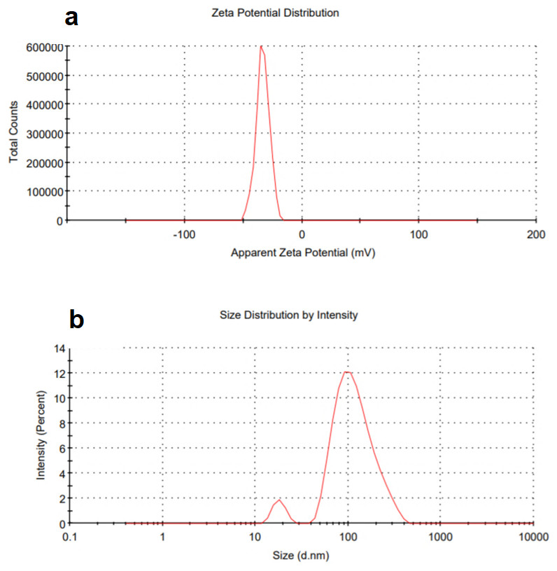
Figure 6: DLS (A) zetapotential and (B) size distribution of green TiO2 NPs.
Thermogravimetric analysis (TGA)
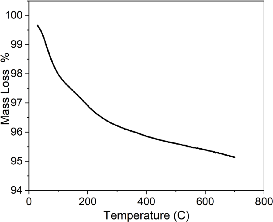
TGA was used to confirm the purity of TiO2 NPs prepared by green approach. The results showed a weight loss in the temperature below 150 °C related to moisture trapped in the of NPs sample (Kashale et al., 2017), as shown in Fig. 7. In addition, the reduction in weight at temperature in the range of 250 to 670 °C. represents the decomposition of organic compounds.
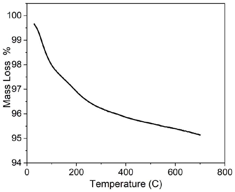
Figure 7: TGA of greenly synthesized TiO2 NPs.
There was a small weight reduction, which is shown in the range of 500–700 °C, possibly due to the loss of residual carbon from the plant (Saranya et al., 2018). The residual was equal to almost 95% of the total weight which indicated highly pure TiO2 NPs.
Photocatalysis activity of TiO2 NPs
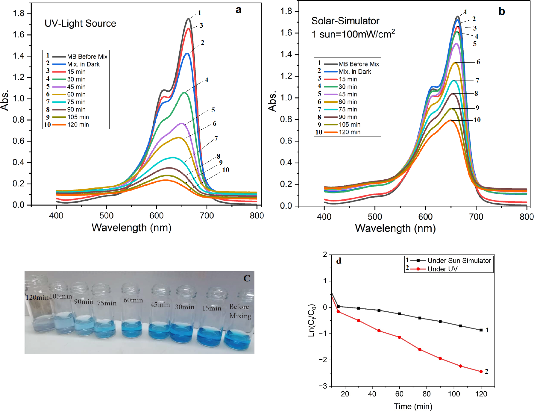
A total of 25 mg of the prepared TiO2 NPs was mixed with 10 mg of methylene blue in 100 mL of distilled water under a UV and other samples under one sun simulator. In a dark room, the mixture solution (Fig. 8C) was constantly stirred. There was no change in color intensity after 30 min. However, as shown in Figs. 8A and 8B there was a slight decrease in peak at the UV–VIS test at 664 nm due to equilibrium sorption and desorption. The photodegradation result is very active under UV and the sun simulator due to MB degradation of and a decrease in MB concentration caused by the photoactivity of TiO2 NPs and capacity the free radical’s capacity to oxidize organic MB. The rate of reaction was calculated using the corresponding kinetic equation, (Ln (Ct/C0) = Kapp * t), where Ct denotes the concentration at time (t), C0 denotes the concentration at time zero, and kapp indicates the apparent rate constant (Haleem et al., 2020; Zahid et al., 2022). Figure 8D depicts the graphical representation of the rate of reaction. The slopes of these plots were used to calculate the values of kapp. Under the same set of reaction conditions, the apparent rate of reaction for the reduction of MB under the sun simulator and UV was found to be −0.00919 and −0.0164 min−1, respectively, which reflects the higher degradation rate of MB under UV.
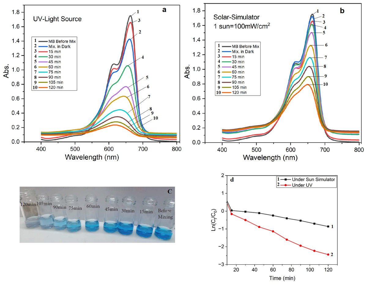
Figure 8: UV after photodegradation activity of green TiO2 NPs under (A) UV, (B) sun simulator, (C) samples color after degradation under UV, and (D) rate constant.
Features and performance of PES, TFC and TFN
Fourier-transform infrared spectroscopy (FTIR)
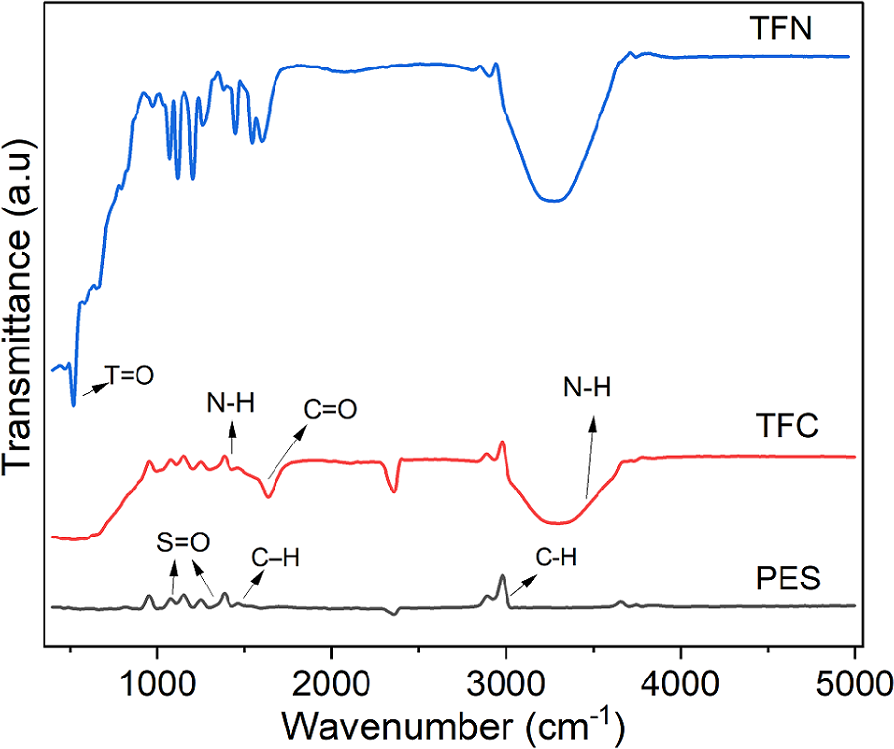
FTIR was used also to verify the introduced thin film and NPs onto the nanocomposite membrane. Figure 9 shows PES, TFC, and TFN FTIR spectra. The PES and PA have bonds around 3100 cm−1 for main aromatic C–H stretches, also at 1500 cm−1 benzene ring stretches, and the S =O bands (1300 and 1150 cm−1) can be noticed. The main characteristic peaks for the PA was observed in TFC and TFN, absorption band at 3300 cm−1 correspond to the N-H stretching, the absorption band at 1480 cm−1 for the N-H bending, and at 1630 cm−1 for the amide C =O stretching bond. An extra peak related to Ti =O NPs around 500 nm is shown in the TFN spectra, which confirm the incorporation of the NPs within the PA polymer matrix (Ahmadi & Jafarizadeh-Malmiri, 2021).
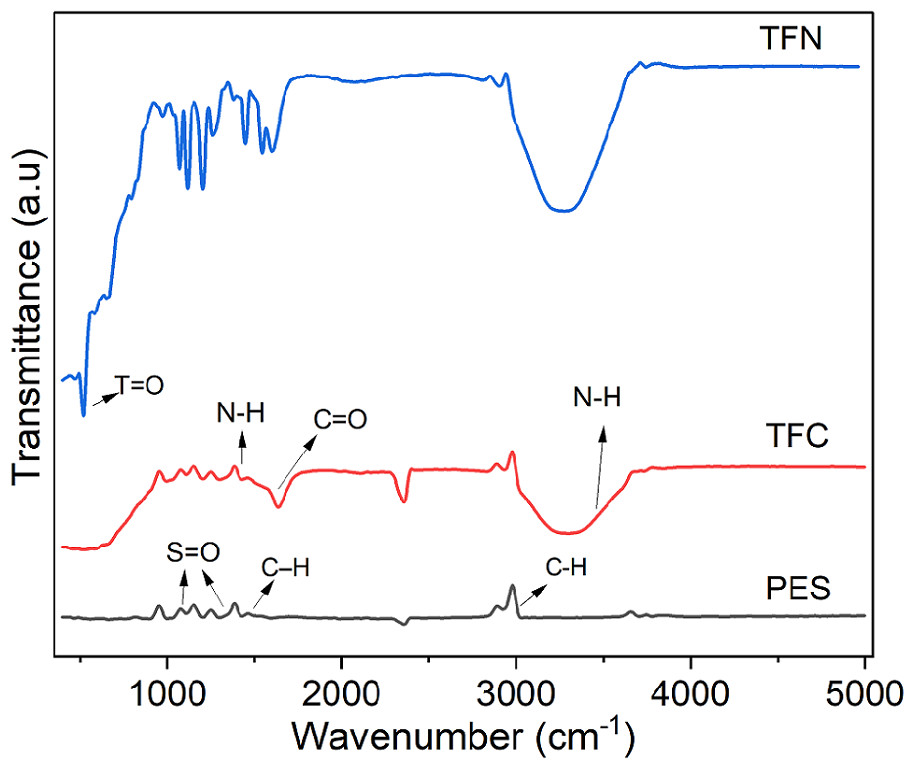
Figure 9: FTIR spectrum for PES, TFC, and TFN.
X-ray Diffraction (XRD) and X-ray Fluorescence (XRF)
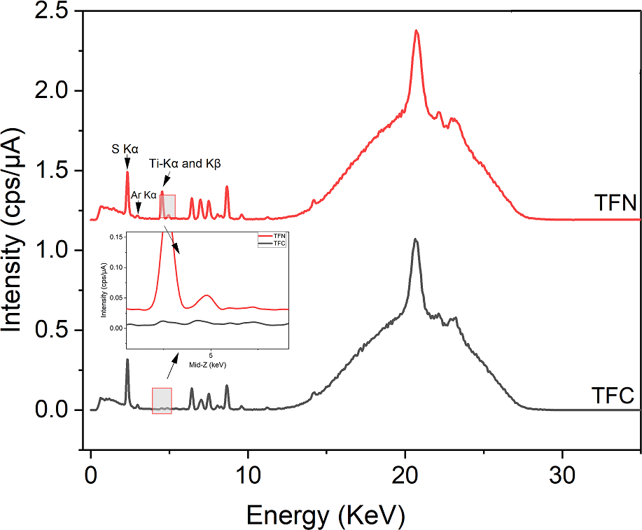
Figure 10 shows the energy dispersive X-ray fluorescence (EDXRF) spectra for TFC, TFN membranes. Based on qualitative comparison, the differences between TFC and TFN membranes spectra was the presence of titanium (previously examined alone as powder; Fig. 4), which confirmed the incorporating the TiO2 NPs within the PA active layer. Both spectra show Ti-K α and Ti-K β signals and non-indexed peaks in XRF patterns are associated with membrane materials (PES and PA) as shown in Fig. 9, this contributed to the successful fabrication of nanocomposite thin film membrane surfaces. The energy peaks in both spectra were around 2.310 and 2.960 related to the distinctive S K α and Ar K α X-ray emission lines respectively; the presence of Ar K α in the spectra was attributed to the amount of Ar in the atmosphere. The presence of S on the PES membrane could be the cause of the measured S, according to an elemental analysis of PES (Chen et al., 2022). It is worth mentioning that some elements such as hydrogen, carbon, and oxygen, cannot be detected by XRF due to their weak fluorescent X-ray. However, polymers are organic compounds containing mainly hydrocarbons, and an XRF cannot be used to analyze the pure polymer (Alqaheem & Alomair, 2020).
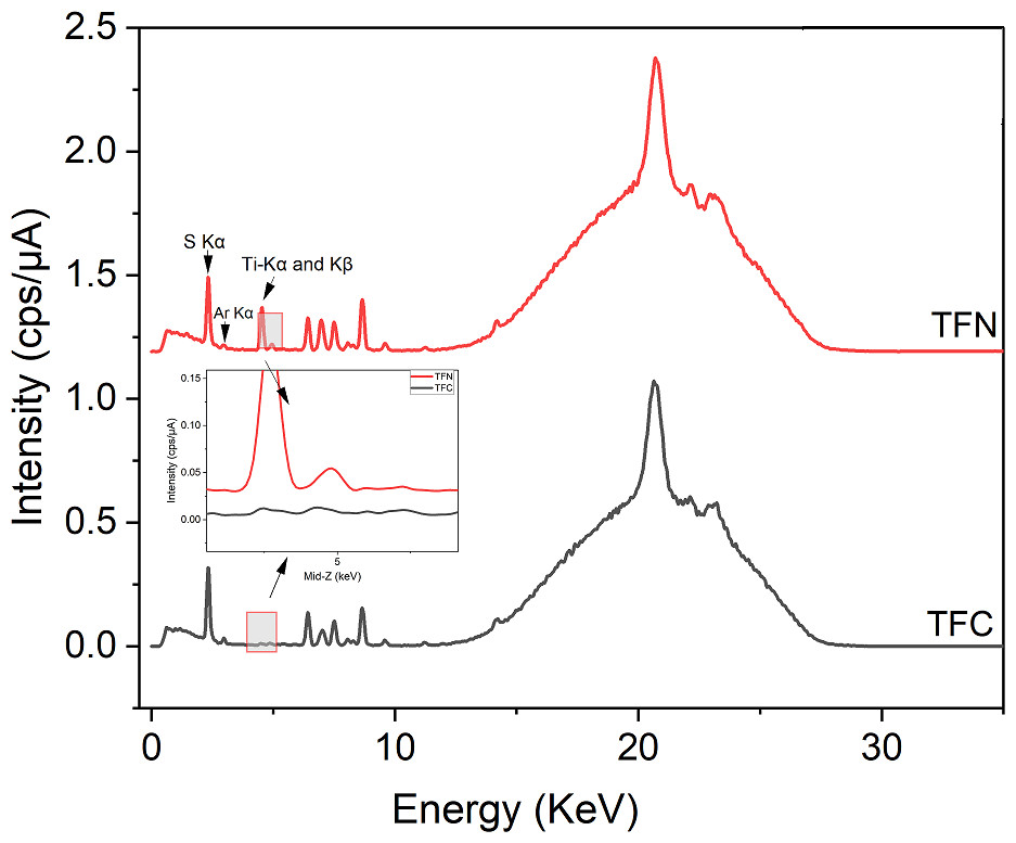
Figure 10: EDXRF spectra of a TFN and TFC membranes.
Scanning electron microscope (SEM)
SEM was used also to investigate the microstructure of the deposited thin film and the effect of TiO2 nanoparticles on the PA thin film microstructure and morphology.
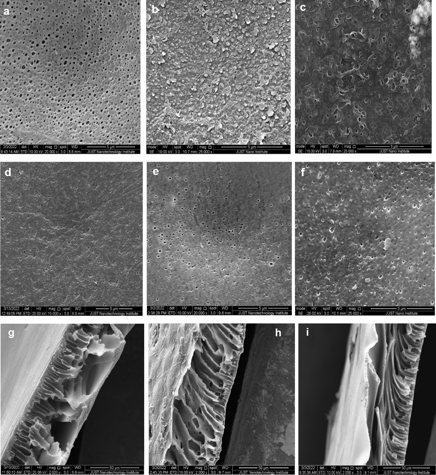
Figures 11A, 11B and 11C show the PES, TFC, and TFN PES top surface, respectively. The tidy PES substrate membrane displayed the featureless, reasonably smooth shape of the surface. The TFC surface displays a typical shape of the ridge-and-valley structure after the interfacial polymerization reaction. Meanwhile, the topography of TFN with 5% TiO2 NPs indicated a reduction in the ridge-and-valley surface shape, due to filling the ridge and valley with nanoparticles according to Asadollahi et al. (2020). An identical bottom SEM images for the PES, TFC, and TFN membrane were clearly shown in Figs. 11D, 11E and 11F; all images show the same porous structure with nearly the same pores and shape due to the fact that all of them have the same substrate (PES) at the bottom surface and the other layers (TFC and TFN) were only added on the top surface of PES. Membranes cross-sections of PES, TFC, and TFN are depicted in (Figs. 11G, 11H and 11I). All membranes are expected to have a characteristic asymmetrical structure. The active layers on top surface in the TFC membranes are distinguished with high roughness in comparison to the PSF membrane and TFN. All cross sections have a sponge-type structure of PES membrane support.

Figure 11: SEM: top images of (A) PSE membrane, (B) TFC, and (C) TFN; Bottom images of (D) PES, (E) TFC, (F) TFN; cross-section images of (G) PES, (H) TFC, and (I) TFN.
Thermogravimetric analysis (TGA)
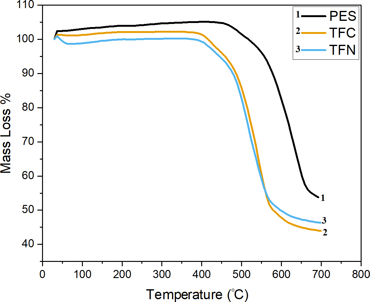
TGA was used also to investigate the effects of membranes modification on their decomposition behavior, and the percentage of TiO2NPs within TFN membranes. Figure 12 depicts the TGA characteristics of PES, TFC, and TFN membranes. The zone that appeared below 400 °C is stable in all samples. The concentration and distribution of TiO2 in the polyamide thin film are probable to be the most significant factors that influence the composite products’ properties. It is hypothesized that the inhomogeneous dispersion of TiO2 NPs at relatively high concentrations may be attributed to the disordering of polyamide chains, thereby minimizing interfacial adhesion between NPs and the polyamide network (Rajaeian et al., 2013).
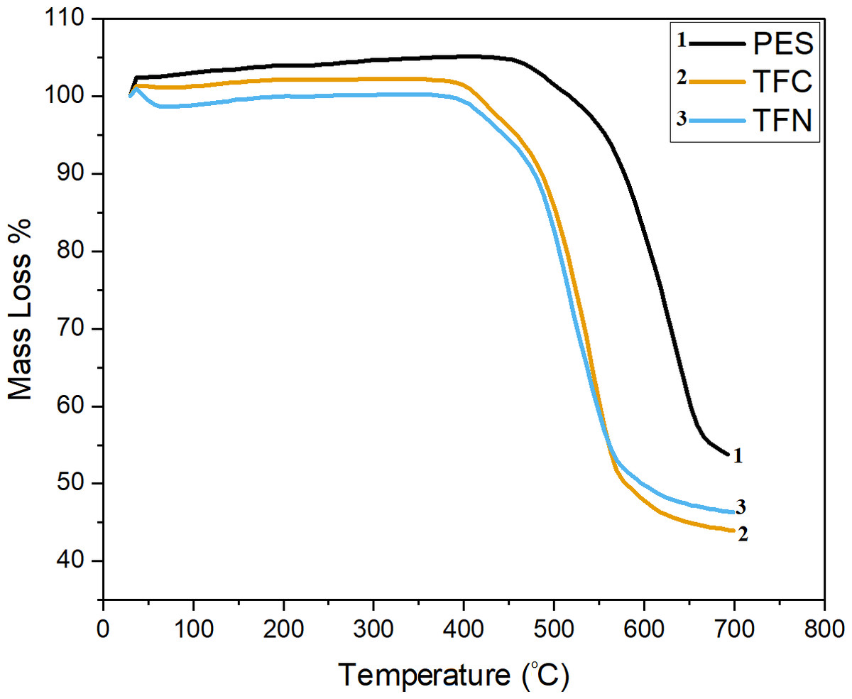
Figure 12: TGA thermographs of PES, TFC, and TFN membranes.
The preliminary area in weight loss for all samples seemed to be below 100 °C, which can be attributed to the evaporation of the residual organic solvent and adsorbed water in composites after drying. After 400 °C, the TFN had less weight loss in the entire temperature range, which can be attributed to the partial dehydroxylation of the TiO2 NPs (Rajaeian et al., 2013). The drop appears at around 500 °C, which is the decomposed heat of PES as the main phase in the membranes. It can be seen that all PES, TFC, and TFN membranes go through primary thermal degradation; at around 500 °C for PES and around 450 °C for TFC and TFN, which could be attributed to the sulfonic group in polymer chains; furthermore, another weight loss stage occurred above 600 °C, which corresponds to the main polymer backbone splitting in the presence of the S =O group, which can be bonded with H2O, causing the formation of intermolecular molecular hydrogen bonds (Kotp et al., 2017). Weight reduction in the TFC and TFN is more constant below 600 °C, as demonstrated by a reduction in mass loss slope associated with carbon molecule detachment above 600 °C. TFN was found to be more stable above 600 °C due to the existence of TiO2 NPs and higher residual at 700 °C (Kotp et al., 2017). The apparent negative mass loss in the TGA thermograph (mass gain above 100%), can be attributed to the fact that the precision and accuracy of the TGA depend on different factors, such as the weight disturbances at the beginning of heating, continuing weight oscillations, miscellaneous observations related to disorders in gases, and erratic buoyancy disturbances. Thus, the first weight deviation of a TG curve typically begins slightly but noticeably before the recorded temperature increases (Czarnecki, 2015).
Atomic Force Microscope (AFM)
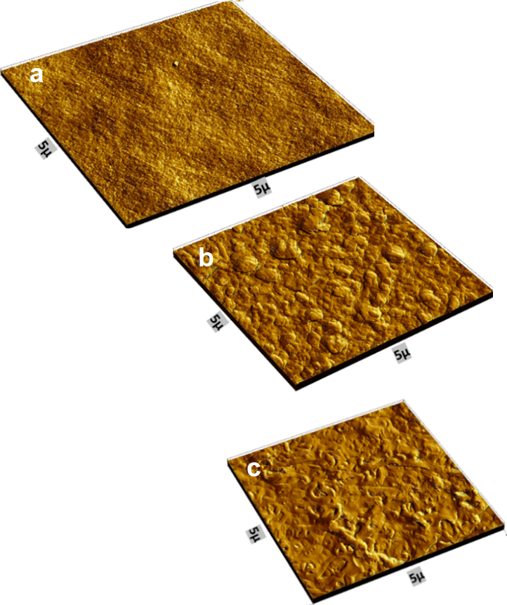
Figure 13 shows the AFM images topography of PES, TFC, and TFN. Table 1 summarizes the average roughness (Ra). The results indicated that polymerized thin film composite (105.8°) membrane has rougher morphologies compared with the PES support membrane (13.5°). For TFC, a uniform distribution of ridge-to-valley morphology can be observed. According to the roughness quantitative data, the TFC membrane has a rougher surface, which is consistent with SEM observations and explains the higher rejection than TFN (43.9°). The SEM and the AFM results are consistent with each other. The same profile of the distribution of the TiO2 NPs in the SEM images are shown in the AFM images. The SEM showed that there was a good distribution of the nanoparticle’s aggregates, which means it is in a poor dispersion, but with good distribution and with the homogenous distribution of the aggregates shown from the AFM images.
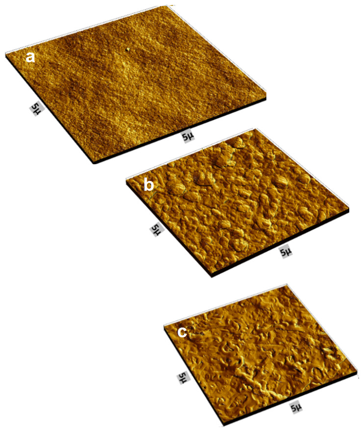
Figure 13: AFM images of (A) PES support, (B) TFC, and (C) TFN.
| Membrane | Average roughness (nm) | Contact angle |
|---|---|---|
| PES | 13.5 | 88° ± 0.8 |
| TFC | 105.8 | 79° ± 1.9 |
| TFN | 43.9 | 72° ± 3.3 |
Drop shape analyzer
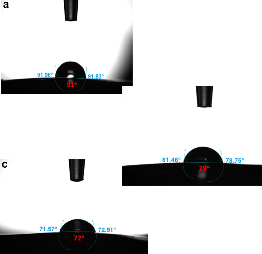
The contact angles of the blend membranes’ surfaces were determined using the sessile drop method. Figure 14 depicts the contact angles of the PES, TFC, and TFN membranes. The PES composite support has the highest water contact angle of 91° so it has the lowest hydrophilic surface when compared to other thin film polymerized membranes (TFC at 79°, and TFN of 72°) which can be attributed to the presence of strong hydrophilic polar amide functional groups inserted onto the PES which increase the hydrophilicity of the PES surface. Because TiO2 nanoparticles are hydrophilic, incorporating NPs within the thin film layer provides a slightly increase in the hydrophilicity of the TFN membrane compared to TFC membrane. The contact angleis in consistence with the roughness results from the AFM, the surface roughness decreased the contact angle for a droplet on a hydrophilic surface and increased the contact angle for a droplet on a hydrophobic surface, according to Wenzel’s equation (Wenzel, 1936), and led to an enhancement of polar interaction with water droplets; thus, a reduction in water contact angle. The results were in consistence with the results of Rajaeian et al. (2013), which can be attributed to the filling of TiO2 NPs in the ridges and valleys; thus the membrane’s surface become smoother.
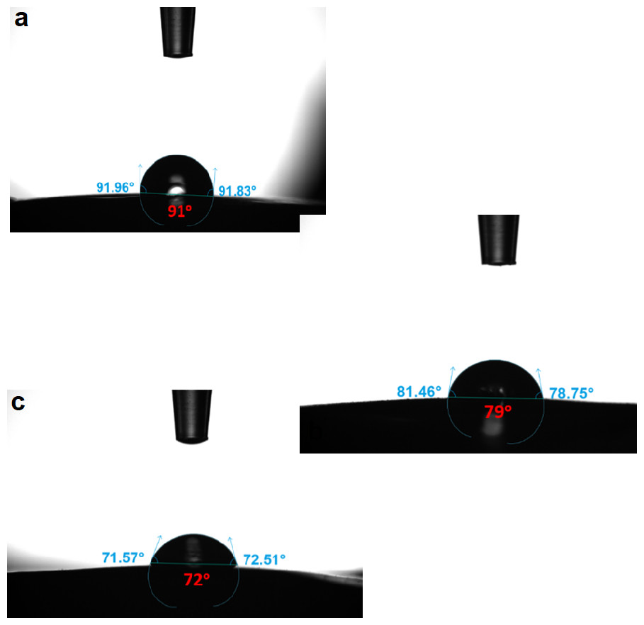
Figure 14: The contact angle of (A) PES, (B) TFC, and (C) TFN.
Membrane performance
The effect of using different salt and different concentrations
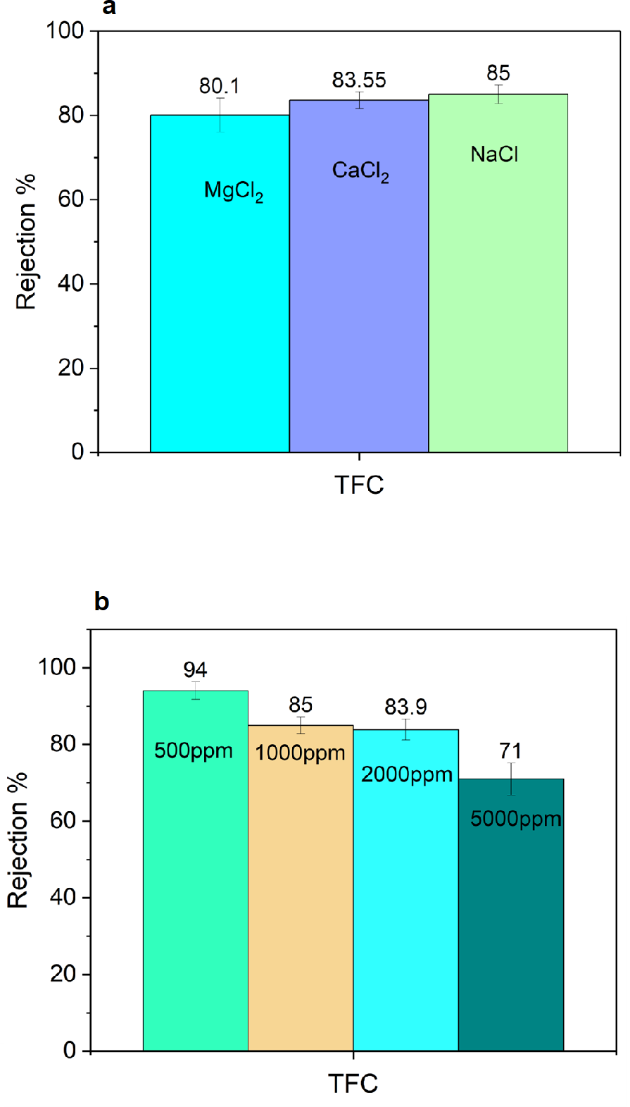
The rejection experiments were carried out using different salts (MgCl2, CaCl2, and NaCl) at a concentration of 1,000 ppm to evaluate the PA membrane’s salt rejection capabilities and they were almost the same in the range of 80–85% rejection (Fig. 15A). Different theories (preferential sorption, electrical) can explain salt transport through a thin film composite membrane (Bhattacharya & Ghosh, 2004). Water preferentially sorbs at the membrane solution interface and then moves through the capillaries of the membrane via viscous flow, with the flux being directly proportional to the effective pressure, according to the preferential sorption theory. Ions move through membrane pores via convection, diffusion, and the electric potential gradient, according to the electrical theory. From a chemical point of view, the formation of -COOH functionality in the cross-linked polyamide is essential for repelling salt and polar compounds. According to Dai et al. (2002), and Joshi, Singh & Bhattacharya (2011), the membranes reject high-valence anions and low-valence cations more than low-valence anions and high-valence cations. Finally, the unexpected higher rejection of sodium chloride for the TFC membrane compared to MgCl2 and CaCl2 is most likely due to diffusion-driven permeation. When the solution reaches a high ionic strength, charge repulsion is screened and molecular size and diffusion become the dominant ion rejection mechanisms which is in consistent with results for Tajuddin et al. (2019); also, the unexpected increase of monovalent ion rejection than divalent ions may be due to their larger hydrated ionic radii, the Mg2+ and Ca2+ ions have high diffusivity of through the membrane according to Gallab et al. (2017). Figure 15B illustrates the effect of different NaCl concentrations. Increasing the salt concentration decreases the rejection. Salt concentration has little effect on flux in the range of 0 to 2,000 ppm and has a greater impact in the range of 5,000 ppm. These findings revealed differences in flux as NaCl concentration increased. Concentration polarization explains the increase in flux values caused by an increase in flow velocities. The mass transfer effect caused by concentration polarization is small at low salt concentrations and easily prevents this effect by a water flow, resulting in no significant change in flux. This is what causes the relatively large variances in flux found in high salt concentrations and small variances in low-range salt concentrations. Our findings agree with those of Krieg et al. (2005) and Koyuncu & Topacik (2003).
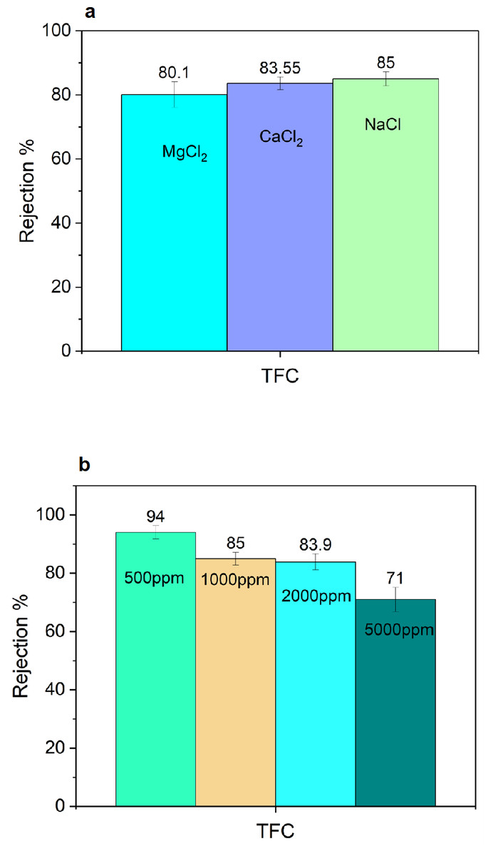
Figure 15: TFC performance: (A) salt rejection for different salts at 1,000 ppm, and (B) effect of different concentrations of NaCl.
Flux and salt rejection
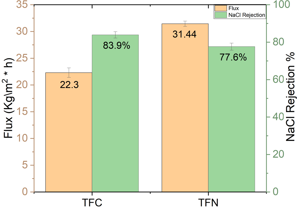
Figure 16 illustrates the flux and salt rejection of TFC and TFN membranes. The hydrophilicity of the TFN increased with high TiO2 NP concentration, but NaCl rejection marginally decreased. The primary factor for immigrating TiO2 nanoparticles on the membrane surface relates to the presence of carboxyl and amide groups following polycondensation which increases the hydrophilicity of the thin film consistently with increasing contact angle. A slight decrease in salt rejection for TFN is assumed to be due to defects formed at the interface of inorganic materials and polymer matrix because of high loading, which is consistent with findings of Kim et al. (2016). With 5% wt TiO2 NPs, flux increased because of the hydrophilic nature of TiO2 NPs, while salt rejection decreased slightly due to the trade-off relationship between water flux and salt rejection (Huang et al., 2013). After the filtration experiment, the mechanical strength of the membranes decreased with critical concentration, resulting in easier peeling of the PA-TiO2 layer from the PES substrate. These findings could be explained by the fact that at high TiO2 concentrations, the interference of interfacial polymerization by TiO2 nanoparticles becomes significant, resulting in a lower degree of polymerization of PA (Lee et al., 2008; Huisman, Prádanos & Hernández, 2000). TFN has higher reversible fouling by 31.15% and lowers irreversible of 16% compared to 28.53% and 38% for TFC. The recovery rate was also increased in TFN upon addition of nanoparticles from 61.77% to 83.2%, while the total fouling ratio was reduced from 66% to 47% due to improving the antifouling properties.
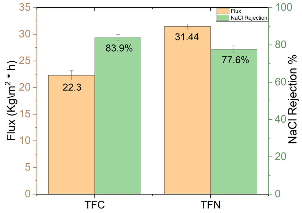
Figure 16: Water flux and 2,000 ppm NaCl rejection for TFC and TFN.
Antifouling performance
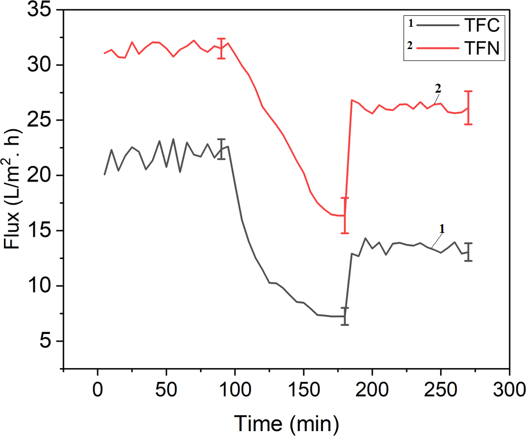
Water flux recovery after fouling with BSA solution was used to analyze the antifouling performance of the pristine TFC and TFN. Figure 17 and Table 2 depict the results for pristine membrane, and TFN. The flux recovery value of a TFC membrane was only 61.77%, indicating its ability for antifouling properties. The flux recovery percentage of the TFN membrane was 83.2%, which was related to a 5% TiO2 membrane. Electrostatic force (Coulomb force), hydrogen-bonding force, hydrophobic force (entropy effect), and Van der Waals forces are the forces that cause proteins to adhere to solid surfaces in an aqueous solution, the TFN demonstrated better antifouling properties due to dissociation by the surface of negative membranes (Yang, Xu & Dai, 2006). The strong electrostatic repulsion force between both negatively charged BSA molecules and the membrane surface improved antifouling effectiveness (Huisman, Prádanos & Hernández, 2000). TFN has higher reversible fouling by 31.15% and lowers irreversible of 16% compared to 28.53% and 38% for TFC. The recovery rate was also increased in TFN upon addition of nanoparticles from 61.77% to 83.2%, while the total fouling ratio was reduced from 66% to 47% due to improving the antifouling properties.
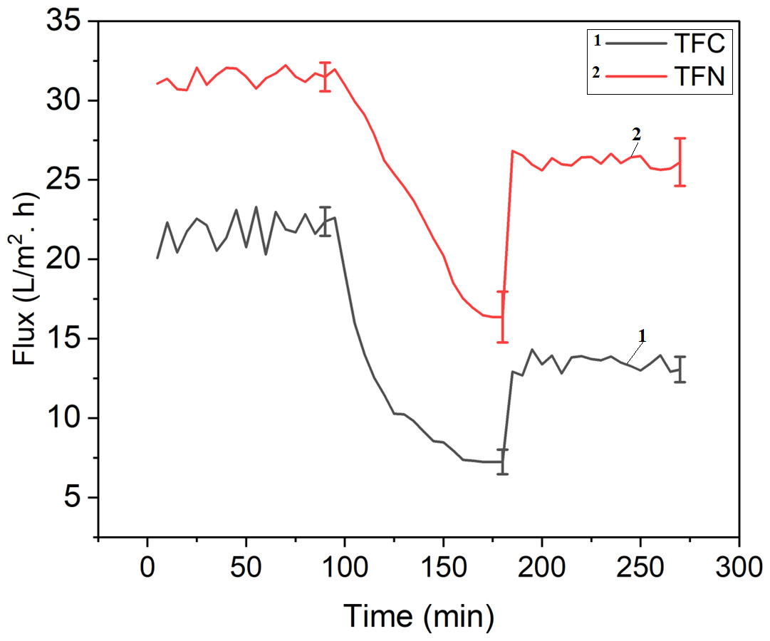
Figure 17: Filtration fouling test with BSA.
| Parameter | TFC | TFN |
|---|---|---|
| Recovery Rate | 61.77% | 83.20% |
| Total Fouling Ratio | 66.75% | 47.94% |
| Reversible Fouling | 28.53% | 31.15% |
| Irreversible Fouling | 38.22% | 16.79% |
Antibiofouling performance
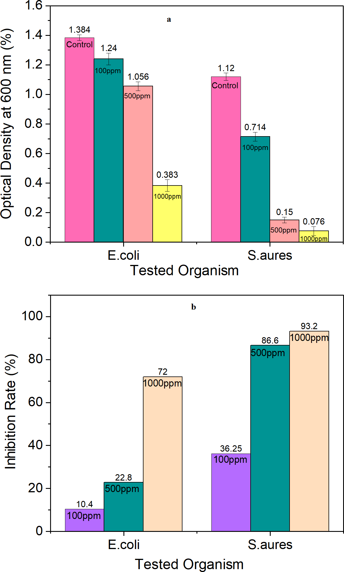
Figure 18A shows the optical density of bacterial culture growths in the presence of TiO2 NPs in a plate reader at 600 nm. The optical density decreased as TiO2 NP concentrations increased in all types of tested patterns. The inhibition rate is shown in Fig. 15B and reaches 72% and 93.2% with 1,000 ppm TiO2 NPs in E. coli and S. aureus respectively. The effect of TiO2 NPs against gram-negative bacteria was less than for gram- positive bacteria due to the difference in membrane structures of bacteria. This effect may be according to mechanism of releasing the free radical according to Khorshidi et al. (2018). Or may be attributed to the fact that metal oxide NPs have a positive charge whereas microorganisms have a negative charge; this produces an electromagnetic attraction among microorganisms and metal oxide NPs, resulting in oxidation and death of the microorganism (Khorshidi et al., 2018; Khashan et al., 2021). The inhibition rate increases with increased NPs concentration, the breakdown of the bacterial surface membrane by reactive oxygen species (ROS), especially hydroxyl radicals (OH), which results in phospholipid peroxidation and ultimately cell death, is the cause of the antibacterial action of TiO2 NPs (Khashan et al., 2021). These ROS can break down organic materials and stop cellular activity with higher activity in gram-positive (Ripolles-Avila et al., 2019).
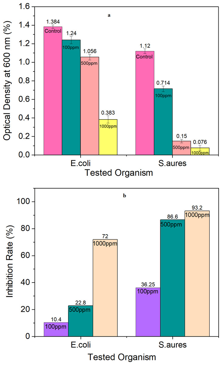
Figure 18: Antibacterial test for TiO2 NPs at different concentrations: (A) optical density at 600 nm, and (B) inhibition rate.
According to the results shown in Table 3, the antibiofouling activity of TFN membrane against Gram-negative (E. coli) and Gram-positive (S. aureus) bacteria was significant with high sterilization ratio of 99.9% TFC has an antimicrobial effect after 24 h of incubation and cultivation according to the nature of polyamide similar the result of Zhai et al. (2020) and Khoo et al. (2021). This could be attributed to TiO2 NPs’ major antibacterial activities. The generation of reactive oxygen species (ROS) is thought to cause bacterial membrane damage and, as a consequence, cell death (Al Mayyahi, 2018). TiO2 affect the cell wall and membrane by damaging DNA and ceasing their replication since bacteria is known to have natural antioxidants and enzymatic antioxidant defense systems that inhibit lipid peroxidation and the effects of ROS radicals. When OH2⋅ − and OH⋅ are exceeded, a set of redox reactions can lead to the death cell by the alteration of different essential structures such as the cell wall and DNA (López de Dicastillo et al., 2020; Abu-Dalo et al., 2019b). Table 4 shows previous research using TiO2 with polyamide membranes, as well as recent studies to solve the problem of fouling. The method of preparing nanoparticles differs in this study, as does the use of a spin coater in the preparation of a thin film substrate for the first time, when compared to traditional by-knife casting, the spin coating process increased solvent evaporation and reduced coat production time as well as reduce the hand person error through casting according to Burmann et al. (2014). When compared to titanium prepared in various ways, we find that the properties are similar in terms of increasing the flow of water and maintaining or slightly decreasing salt rejection. As shown in Table 4, nanoparticles such as silver and copper have recently highly contributed to improving fouling resistance by up to 90%.
| Membrane | (E. coli) Bacteria (ATCC no. 8739) | (S. aureus) Bacteria (ATCC no. 25913) |
|---|---|---|
| TFC control | 16528 Bacteria/cm2 | 206.6 Bacteria/cm2 |
| TFN after incubation (Treatment with TiO2 NPs) | 10 Bacteria/cm2 | 10 Bacteria/cm2 |
| TFC after incubation (Effect of TFC) | 124 Bacteria/cm2 | 41.3 Bacteria/cm2 |
| Sterilization Ratio of TFN | 99.9% | 99.9% |
| Reference | Materials | Method | Results |
|---|---|---|---|
| Kwak, Kim & Kim (2001) | PA/TiO2 NPs on polysulfone supports (commercial) | TiO2 Synthesis by sol–gel and IP for thin film | Water flux increased by 10%, with no change in salt rejection at 2000 ppm NaCl. The photocatalytic bactericidal efficiency of the TiO2 hybrid was noticeably higher. |
| Khashan et al. (2021) | TiO2 NP particle sizes ranged from 2 to 23 nm, with spherical shapes | TiO2 NPs synthesis by liquid laser ablation in a single step | The optimum activity of TiO2 NPs is found to be against E. coli and S. aureus at 1000 ppm with inhibition rates of 81% and 90% respectively. |
| Lee et al. (2008) | PA/TiO2 NPs (commercial) | PSF by PI via casting knife and coated with polydopamine/IP for thin film | The flux increased with 5.0 wt% TiO2 NPs, while MgSO4 (2000 ppm) rejection decreased sharply 95% at 5% TiO2 |
| Kim et al. (2016) | PA/TiO2 NPs on polysulfone (PSF) ultrafiltration (UF) support (commercial) | different TiO2 NPs incorporation methods/TiO2 Synthesis by sol–gel | Increased water flux by ten times, improved antifouling properties (BSA fouling test), and rejections of 2000ppm NaCl above 94% with 5–10% NPs. |
| Yang et al. (2021) | PA/alumina nanoparticles (Al-NP) on polysulfone | membrane fabrication method included a poly (3-sulfopropyl methacrylate potassium salt)-AgNPs brushes grafting step | Increased flux did not affect salt rejection, which remained between 90 and 92.5%, and high biofouling resistance, which reduces BSA attachment by 84%. |
| Justino et al. (2021) | PA/sulfonated polyelectrolyte-silver nanoparticle on polysulfone (PSF) support | IP for thin film composite | Rising membrane flux (40%) and antifouling property at the same time After 4 days of immersion in Escherichia coli bacterial solution, the maintained flux ratio (anti-biofouling property) significantly increased. |
| This Study | PA/Green TiO2 NPs on PES support | PES prepared by spin coater/thin film via IP | Increased water flux by 41% and slightly declined in NaCl 2000ppm rejection by 7% with 5% NPs. Increasing antifouling resistance with BSA fouling test and reduced BSA attachment by 22% with higher antibiofouling compared to TFC |
Conclusions
Fouling has been identified as the primary cause of the membrane’s performance degradation. This study created a hybrid TFN membrane with antifouling properties using greenly synthesized TiO2 NPs, in which TFN membranes were made using the phase inversion method, while the active layer polyamide was made using interfacial polymerization.
In this study, TiO2 nanoparticles was successfully prepared in pure crystalline anatase phase with 10 nm size. Green synthesis method was used in which thyme plant extract was used as both a reducing and capping agent in the production method. The prepared TiO2 nanoparticles were used as an antifouling agent and embedded successfully within the polyamide thin film nanocomposite layer. The overall membrane performance was enhanced; the water flux was increased up to 31.4 comparing with 22.3 (Kg/m2 h) for the membrane without the nanoparticles; slightly decrease in salt (NaCl) rejection was observed from 83.2% to 77.6% but with enhancement in antifouling properties; an increase in the recovery rate was also observed from 61.77% to 83.2%. In addition, TFN membranes showed antibacterial activity against both bacterial strains, with a sterilizing ratio of 99.9%, which improved membrane anti-biofouling behavior.