
Triple Modular Redundancy verification via heuristic netlist analysis
- Published
- Accepted
- Received
- Academic Editor
- Mary Sheeran
- Subject Areas
- Computer Aided Design, Computer Architecture, Embedded Computing
- Keywords
- Single event effects, Triple Modular Redundancy, Verification
- Copyright
- © 2015 Beltrame
- Licence
- This is an open access article distributed under the terms of the Creative Commons Attribution License, which permits unrestricted use, distribution, reproduction and adaptation in any medium and for any purpose provided that it is properly attributed. For attribution, the original author(s), title, publication source (PeerJ Computer Science) and either DOI or URL of the article must be cited.
- Cite this article
- 2015. Triple Modular Redundancy verification via heuristic netlist analysis. PeerJ Computer Science 1:e21 https://doi.org/10.7717/peerj-cs.21
Abstract
Triple Modular Redundancy (TMR) is a common technique to protect memory elements for digital processing systems subject to radiation effects (such as in space, high-altitude, or near nuclear sources). This paper presents an approach to verify the correct implementation of TMR for the memory elements of a given netlist (i.e., a digital circuit specification) using heuristic analysis. The purpose is detecting any issues that might incur during the use of automatic tools for TMR insertion, optimization, place and route, etc. Our analysis does not require a testbench and can perform full, exhaustive coverage within less than an hour even for large designs. This is achieved by applying a divide et impera approach, splitting the circuit into smaller submodules without loss of generality, instead of applying formal verification to the whole netlist at once. The methodology has been applied to a production netlist of the LEON2-FT processor that had reported errors during radiation testing, successfully showing a number of unprotected memory elements, namely 351 flip-flops.
Introduction
At high altitude or in space, without the protection of the earth’s magnetic field and atmosphere, integrated circuits are exposed to radiation and heavy ion impacts that can disrupt the circuits’ behavior. This paper focuses on Single-Event-Upsets (SEUs), or soft errors, usually caused by the transit of a single high-energy particle through the circuit. In particular, we consider single bit flips in memory elements embedded in logic, implemented as flip-flops. Protection against SEUs can be obtained in several ways, and in particular this work considers the protection strategy based on the triplication of the storage elements of a circuit, combined with majority voting (Carmichael, 2006), usually referred to as Triple Modular Redundancy (TMR).
TMR can be either implemented during high level design (Habinc, 2002) or at a later stage by automatic netlist modification. Typically, after a new radiation-tolerant ASIC is produced, it undergoes a strict test campaign, including costly and time consuming radiation tests using particle accelerators. When a problem linked to the radiation effects protection logic arises during a radiation test campaign, it is already too late; the first prototype ASICs have been manufactured and the whole fabrication process needs to be rerun. Detecting this kind of problems before fabrication is key, therefore several software (Kanawati & Abraham, 1995; Boué, Pétillon & Crouzet, 1998; Maestro, 2006; Goswami, Iyer & Young, 1997) and hardware-based (Aguirre et al., 2005) tools for fault injection and protection verification have been proposed in the recent past. However, such tools usually are not designed to provide full SEU protection verification, and require extremely long simulation and/or execution times when attempting comprehensive fault injection and analysis campaigns. To the best of the author’s knowledge, no commercial or academic tool providing TMR implementation verification is currently available.
This paper presents a novel way to verify the TMR implementation of a given circuit by executing a heuristic netlist analysis. Our goal is to verify that TMR constructs are insensitive to single bit flips (i.e., the logic is triplicated), and transients on clock or reset (i.e., there are no common reset/clock lines between redundant memory elements). To reduce execution time, we use a divide et impera approach, splitting the netlist in smaller submodules, without loss of generality. Results show that verifying TMR on a 40k gates netlist is possible within around half an hour on a standard PC. As this work is based on formal analysis, our approach does not rely on a testbench, allowing a full coverage test based solely on the device netlist.
This paper is organized as follows: previous works on the subject are introduced in ‘Previous Work’; ‘Proposed Approach’ details the algorithm together with necessary definitions, its implementation and its complexity; experimental results are shown in ‘Experimental Results’, and ‘Conclusions and Future Work’ draws some concluding remarks.
Previous Work
In the past, different approaches have been proposed for design verification against soft errors. These approaches can be divided in two kinds: fault injection simulation and formal verification.
Fault injection simulators run a given testbench on the design under test (DUT), flipping either randomly or specifically targeted bits. The outputs of the DUT are then compared with a golden model running the same testbench, and discrepancies are reported. Fault injection simulators come in two different flavors: on the one side there are software-based simulators like MEFISTO-L (Boué, Pétillon & Crouzet, 1998) or SST (Maestro, 2006) (which is based on Modelsim), that allow full observability and control of the simulated netlist. These tools are marred by extremely slow low-level simulation, requiring hours or days of simulation, making them unsuitable for full coverage tests. On the other hand, some tools use special hardware to speed up the simulation cycle, such as FT-Unshades (Aguirre et al., 2005), which uses partial reconfiguration of an FPGA to quickly introduce bit-flips (simulating SEUs) without requiring modifications of the DUT. Although this provides a consistent speedup compared to the software based approach, it is still unfeasible to run exhaustive verification of a typical ASIC design in full, which would require the injection of bit flips in all possible Flip-Flops (FFs) at any possible time during the simulation. It is also worth noting that the results of these approaches and how they can be interpreted strongly depend on the testbench used.
Formal verification against soft-errors was introduced by (Seshia, Li & Mitra, 2007): the idea is to merge a formal model of the DUT with a soft error model, proving a given set of properties on the merged model. This requires a formal model of the DUT and a complete and exhaustive set of formally defined properties to be proven. In other words, the main issue of this formal approach is that the coverage is as good as the definition of such properties.
This work tries to overcome these limitations and provide full verification of a TMR-based DUT with reasonable analysis time. The idea presented in this paper can be classified as a fault-injection simulation, but follows a different approach as compared to previous work: instead of trying to simulate the whole circuit at once and doing a timing accurate simulation, we focus on a behavioral, timeless, simulation of small submodules, extracted by automatic analysis of the DUT internal structure, with the specific goal of detecting any triplicated FF that is susceptible to the propagation of SEUs in the DUT.
Proposed Approach
The starting point of our analysis is a radiation hardened circuit, protected by triplication of storage elements and voting (TMR in Carmichael (2006)). Our objective is to verify that indeed all FFs are adequately protected, and no issues were introduced, for example, by synthesis or routing tools.
Starting from a given design with n FFs, a naive testing approach for SEU-sensitive FFs would require injecting faults in all 2n possible FF configurations, for all of the m time instants of a given testbench. This would lead to an impractically long simulation time, as typical systems consist of several thousand FFs. Our approach performs a behavioral fault injection, splitting the whole system into smaller submodules, that can be analyzed independently, allowing full verification to be carried out in a reasonable timeframe.
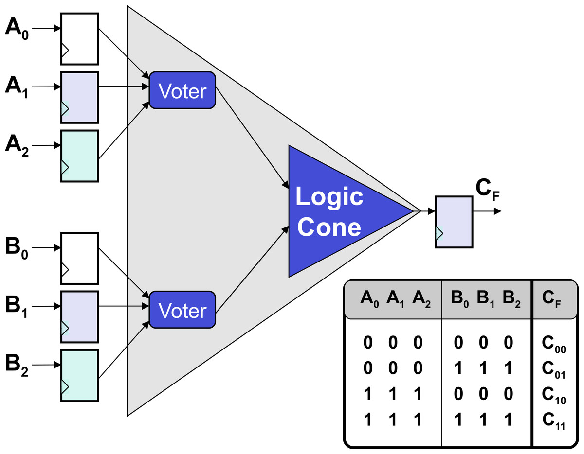
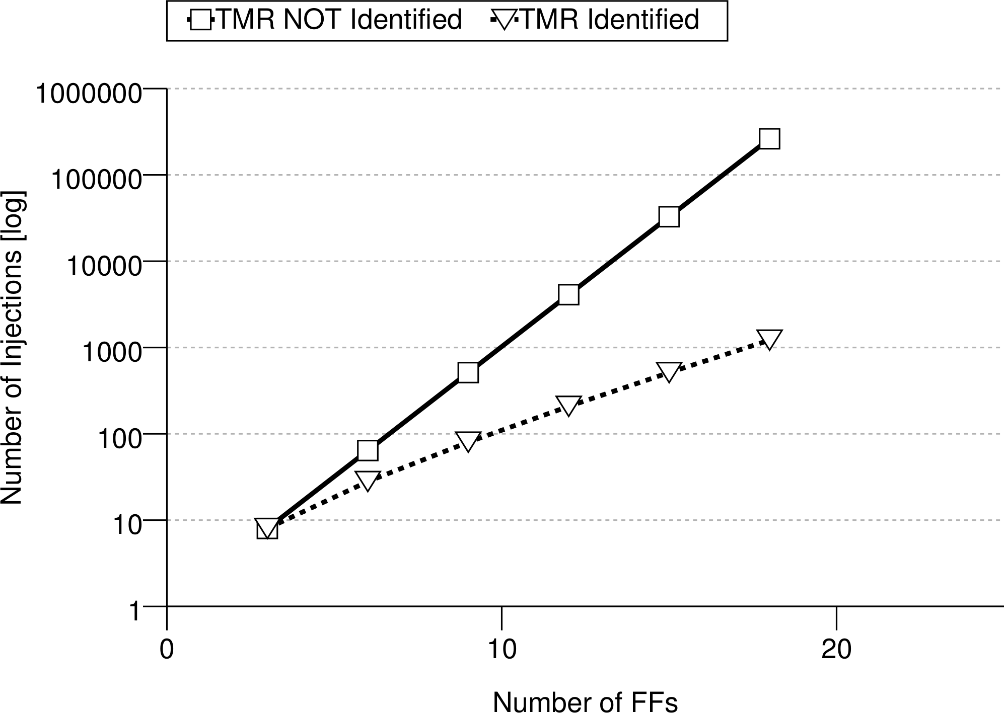
These submodules are the logic cones driving each FF. A logic cone is a set of combinational logic bounded by FFs and I/O (see Fig. 1). To verify that no FF are sensitive to SEUs (therefore assuring the correct TMR implementation), it is possible to extract its driving logic cone, and perform an exhaustive fault injection campaign. This means that the FFs bounding the logic cone are injected single bit flips in all possible input configurations, comparing the output of the logic cone with its expected (i.e., fault-free) one. It is also necessary to verify that all the triplicated FFs have separate asynchronous reset and set lines, otherwise a transient on one of these lines might still cause a failure in the circuit. Testing all possible configurations for a logic cone means 2nf injections, with nf the number of driving flip-flops making the analysis difficult or impossible for high nf. When TMR is applied to each memory element, nf increases by a factor 3 in each logic cone, and the cone itself is modified to account for the voting logic, as shown in Fig. 2. However, when a TMR implementation is present, each logic cone is driven by triplets of flip-flops and Fig. 2 shows how his restricts the number of input configurations that are actually valid for the cone, as all FF belonging to the same triplet share have the same value during normal operation of the circuit. The proposed algorithm, considering only valid configurations when performing fault injection, reduces the number of injections to 2nf(1 + nf), with nf the number of driving FFs for each logic cone. This results in a considerable analysis speed-up: Fig. 3 shows the trend for the number of injections needed as nf increases.
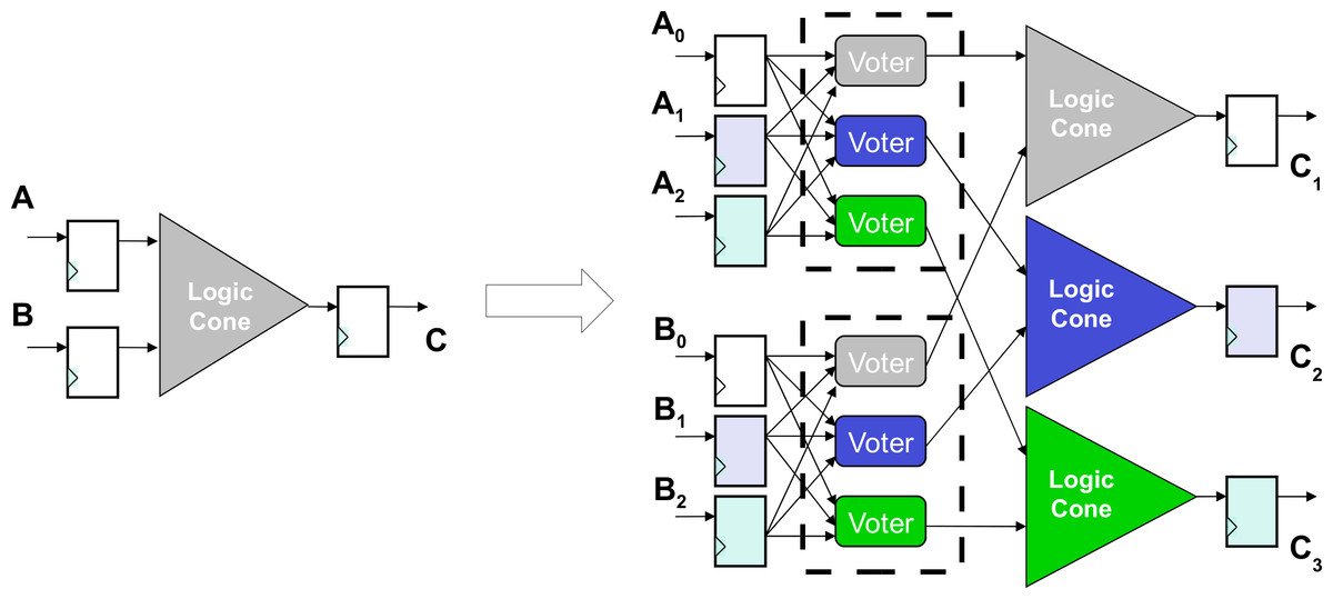
Figure 1: A logic cone is a set of logic bounded by FFs and I/O.
When TMR is applied, each logic cone contains part of the voting logic.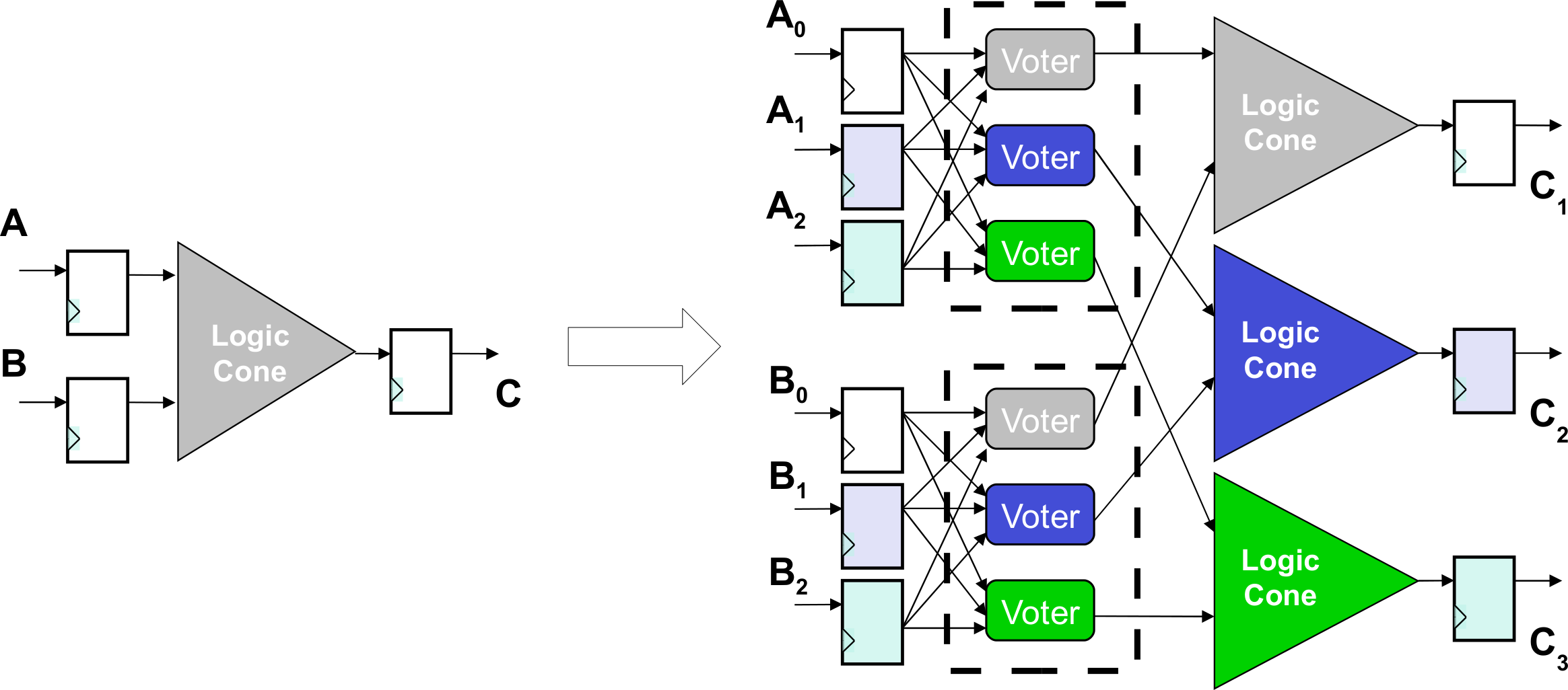
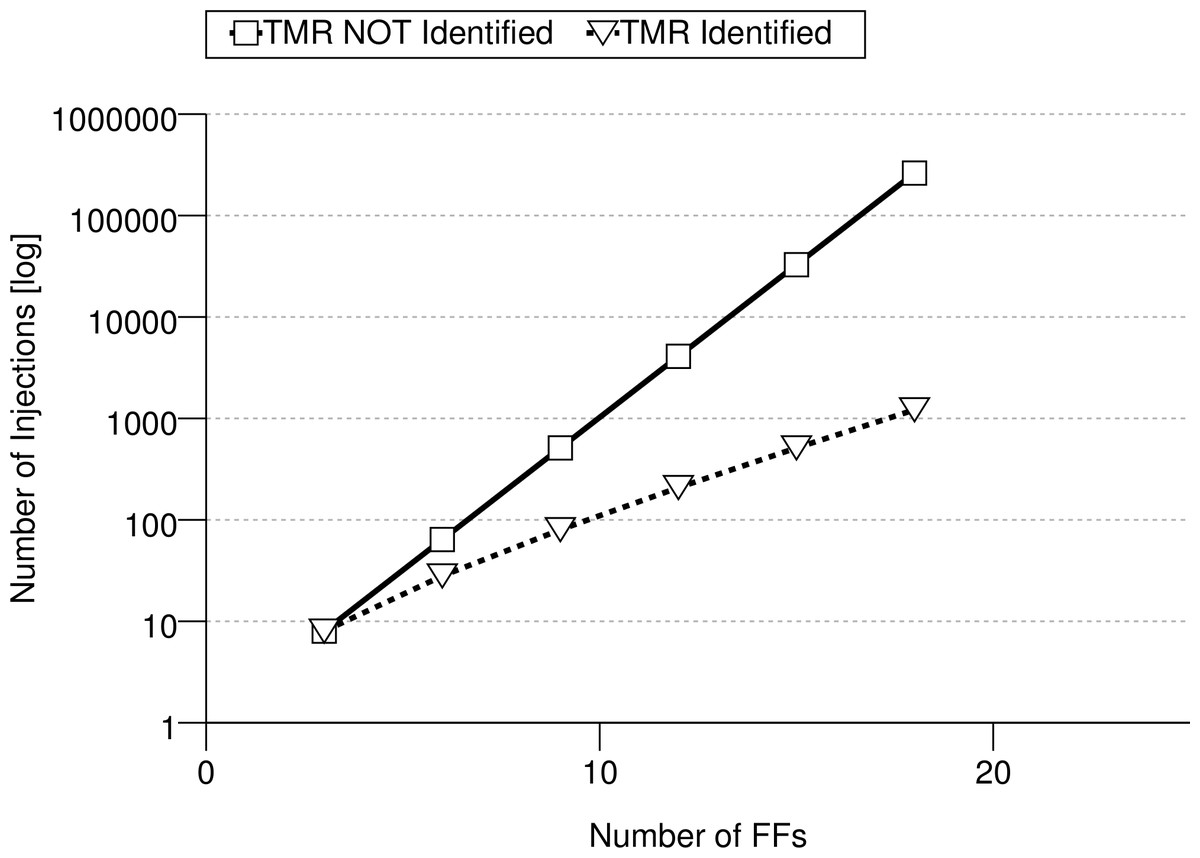
Figure 3: Trend for the number of checks needed per for a logic cone with as the number of driving FFs increases.
The methodology here presented relies on some assumptions: the whole circuit is driven by only one clock and there are no combinatorial loops. Furthermore, it is assumed that there are no signal conflicts inside the netlist (i.e., two-valued logic) and that there are no timing violations. Finally, we assume that all FFs have one data input and one clock source.
Mathematical model
To describe the algorithm, we need to introduce a special directed graph structure. The nodes of this graph have indexed inputs and are associated to a logic function and a value, as outlined in the following. We assume without loss of generality that every gate has just one output. Gates that have n ≠ 1 outputs are converted into n nodes having the same inputs, each representing one output. Taking this into account the netlist can be easily converted into a directed graph structure
A circuit graph G is defined as a tuple {V, E, S, F}, where:
V is a set of nodes (representing logic gates)
E ⊆ V × V × ℕ0 is a set of edges (representing interconnection wires)
S ⊆ V × {0, 1} is a set of values (representing the node values)
is the set of logic functions associated to each node, where is the set of computable boolean functions
The set of direct predecessors of node x, i.e., the set of nodes with a direct connection from their output to one of x inputs is defined as:
Let us define the predicate is_f f for a given node x ∈ V, which determines if x represents a FF:
We define the set of nodes which are directly and indirectly connected to the inputs of a given node x ∈ V as the smallest set pre_f fs(x) for which the following properties hold ∀w ∈ pre(x):
A driver for FF x ∈ VFF is defined as:
The value of a node x ∈ V is given by the eval operator, defined as: where evalFF returns the value stored in FF x: and evalL computes the value of logic (i.e., non FF) nodes, which depends on the node input values: We also define the configuration of a set of FFs {x1, x2, ..xn} ∈ VFF as A configuration config(x1, …, xn) is defined as valid when two FFs driven by the same logic value share the same value for all configurations: with ≡ being defined as functionally identical (see Definition 7).
The proposed methodology is composed of 3 steps:
-
Triplet identification: determine all the FF triplets present in each logic cone
-
TMR structure analysis: perform an exhaustive fault injection campaign on all valid configurations
-
Clock and reset tree verification: assure that no FF triplet has common clock or set/reset lines
These steps are detailed in the following.
Triplet identification
To determine a useful set of valid configurations for a logic cone (here represented by a subgraph), it is necessary to identify which FFs are triplicated, as all the FFs belonging to a triplet have to share the same value. However, the gate naming scheme is usually insufficient. A base assumption for triplet identification is that all triplicated FFs are driven by the same source. An algorithm based on this fact is able to find most triplets, but this simple mechanism is not always sufficient for more complex netlists.
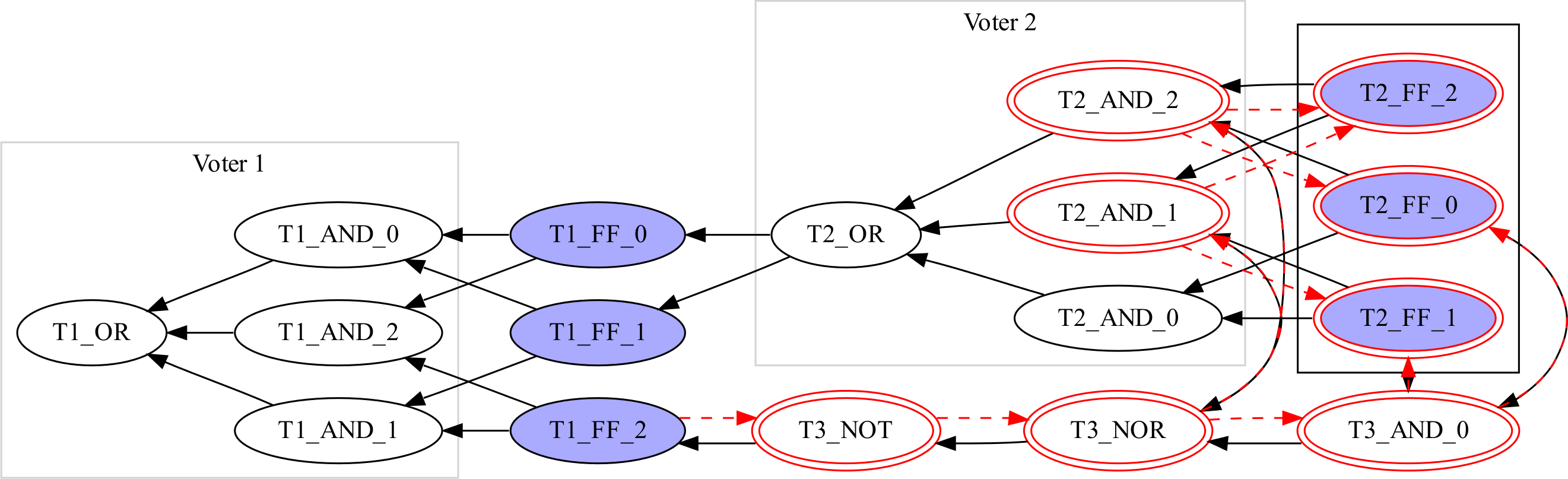
During synthesis, netlists are often optimized in a way that voids this property. Figure 4 shows an example: Voter 2 was partially duplicated using other logic elements, with T2_OR and T3_NOT delivering the same values for all configurations of T2_FF_*, thus leaving T1_FF_2 with a different set of inputs with respect to the other members of the triplet. The synthesizer introduces this redundancy for delay optimization, place and route constraints, etc. Therefore, we assume that two FFs belong to one triplet if they are both driven by functionally identical nodes.
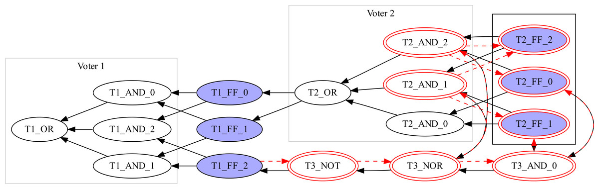
Figure 4: A sample graph with FF triplets and voters after optimization.
Two nodes x1 and x2 are functionally identical (x1 ≡ x2) if pre_f fs(x1) = pre_f fs(x2) and eval(x1) = eval(x2) for all possible configurations of pre_f fs(⋅).
Testing for functionally identical inputs requires equivalence checking (Thornton, Drechsler & Gunther, 2000) of the logic functions expressed by the nodes. For the sake of simplicity we implemented a simple checker that exhaustively compares all possible input configurations for the two nodes. Checking the equivalence between two nodes might be impractical, as the problem grows exponentially (roughly 2pre_f fs(x)). However, wrong triplet identification affects the verification of TMR protection only with the reporting of false positives, i.e., reporting a faulty triplicated structure when none exists. Therefore, we propose a heuristic algorithm in three steps.1 Let us consider the example of Fig. 4, where Algorithm 1 is applied to T1_FF_2 and T1_FF_1 (x and y in the algorithm, respectively). Two sub-algorithms are needed:
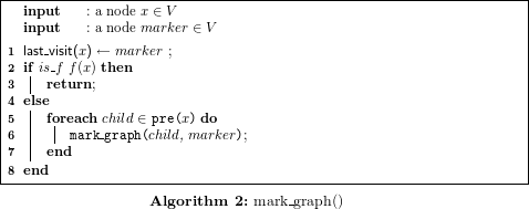
mark_graph(x) traverses the graph starting at node x and marks all visited nodes, stopping at FFs. Its behavior is formalized in Algorithm 8.
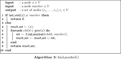
find_marked(y, x) traverses the graph depth-first starting from y until a FF is encountered and returns all the nodes that were found as marked by x. Its behaviour is formalized by Algorithm 10.
The first step checks the sets of driving FFs for equality (lines 1–3) before starting from x (Fig. 4, T1_FF_2) and traversing the graph depth first, marking all visited nodes (shown as a second circle in Fig. 4), until a FF is visited and marked (line 4).
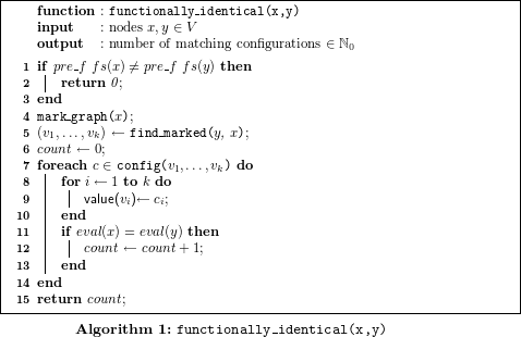
In a second step the algorithm starts again from y (Fig. 4, T1_FF_1) and traverses the graph until reaching a marked node. If an unmarked FF is traversed, this shows that x and y are not functionally identical2 in the same clock cycle, and the algorithm aborts. After terminating successfully, the algorithm returns the set of marked nodes (Alg. 1, line 5). For the example in Fig. 4 this would be T2_AND_1, T2_AND_2, T2_FF_2.
The third step verifies that all configurations for this set have the same values for x and y. This is done by assigning all possible configurations to this set (Alg. 1, lines 7–10) and evaluating the subgraph for x, y to compare the results (line 11). Checking all possible configurations, as opposed to only valid ones, might result in functionally identical nodes not being recognized. Instead of drawing a sharp yes/no conclusion, the number of matching configurations is compared for all possible triplet allocations, and the best one is used to assign the FFs. In other words, the nodes xi and xj belong to the same triplet for which i and j (i ≠ j) result in the largest number of matching configurations.
It is worth noting that the worst case scenario for this fast heuristic, i.e., when all FFs are reported as false positives, is when both subgraphs share only the driving FFs and the whole subgraph is duplicated. This is unlikely to happen when analyzing real world netlists, because synthesizers optimize away most redundant parts and introduce redundancy only in rare cases. For the designs used in this work, the non-shared subgraph size is typically less than nine gates as shown by Fig. 7.
TMR structure analysis
Before starting the analysis, we optimize our description by removing non-relevant elements, as one-to-one buffer gates. As such buffers do not manipulate the logic value of a signal, it is easy to see that the logic functions are not changed when they are removed.
If the TMR implementation were working correctly, a single bit-flip in one FF should not cause another FF to change its value. If a faulty triplicated FF/voter pair exists, there is at least one FF whose value can be changed by a single bit-flip in another FF. This is true only if the configuration before the bit-flip injection was a valid configuration. The algorithm tries to find such FFs, and if none are found, TMR is correctly implemented.
The main idea of the test algorithm is that complexity can be reduced by checking only small submodules instead of the whole system. In order to do this, we observe that a bit-flip in one FF can only distribute to the next FF during the current clock cycle. It is then possible to determine the set of all FFs which could potentially influence a given FF x ∈ VFF, i.e., pre_f fs(x), i.e., the FFs driving x’s logic cone.
The algorithm takes each FF xi and determines the set of FFs that driving its logic cone, and tests every possible bit flip for every possible valid configuration. If any of these bit flips is able to change xi stored value, then the algorithm detected a fault in the TMR implementation. More formally, Algorithm 4 describes this behavior in pseudocode (where abort interrupts execution and shows a message to the user). As the analysis
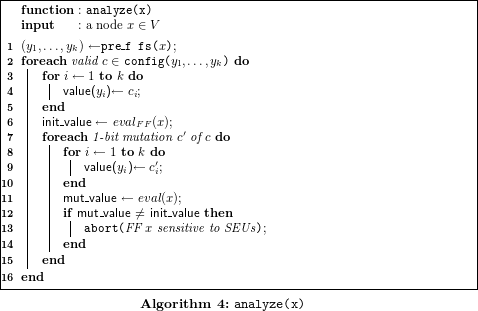
has to be performed for all x ∈ VFF, analysis times might be excessively long. To reduce runtime, this algorithm has to be extended to handle large sets of driving FFs (y1, …, yk). If the number of elements t = |pre_f fs(x)| in such a set exceeds a given threshold, the graph will be split into smaller subgraphs until the threshold is reached, as outlined in ‘Splitting algorithm’.
Splitting algorithm
Analyzing typical designs with the proposed algorithm showed that the majority of FFs are driven by a very small set of FFs pre_f fs(x) (typically less than 9, see Fig. 7). However there are a few FFs that are driven by a large number of FFs (for some designs 500 or more). Those subgraphs cannot be analyzed directly as they require 2n configurations to be evaluated, and heuristics have to be devised.
A naive approach would use “divide et impera,” splitting every node where |pre_f fs(yi)| > threshold, starting from the FF to be analyzed. It is worth noting that the count from Algorithm 15 is not what is used here as a threshold. Here we consider only the number of driving flip-flops, and not the number of matching configurations between two logic cones. This approach works for most FFs but fails if the synthesizer merged a voter with other logic during optimization. As an example, a 3-OR gate of a voter might be merged with a following OR gate into a 4-OR gate. Splitting could break the voter and result in a false positive alert.
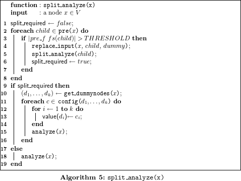
Let childi be the nodes connected to the inputs of node x. To avoid breaking voting logic, instead of splitting using the threshold only, the originating node is kept and the subgraphs for the nodes childi with |pre_f fs(childi)| > threshold are replaced by dummy input nodes (Alg. 5, lines 3–7). Every Node childi is tested recursively according to Algorithm 4 with the divide et impera approach.
Afterwards, all possible bit configurations are assigned to the dummy inputs connected to x (lines 12–14). Analyzing x for such configurations ensures that x is tested for all possible substates previously generated by the removed nodes childi.
It is worth noting that this heuristic relies on the fact that synthesizers tend to keep the voting logic close to the originating FFs, and therefore splitting subgraphs with a large number of inputs usually does not result in voters to be broken.
However, it cannot be excluded that some voting logic might be broken, resulting in some rare false positive alerts (see ‘Experimental Results’). This will never hide any SEU sensitive parts: if TMR is not properly implemented, this will be detected. In case the algorithm reports a SEU-sensitive FF, testing with a higher threshold value or manual inspection can identify if it represents a false positive.
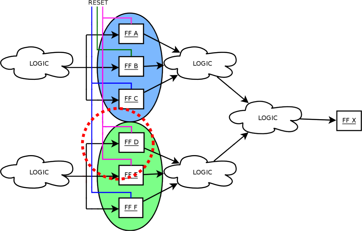
Clock and reset tree verification
Verifying that the voters are correctly performing their task is not sufficient to guarantee that TMR structures are working. One also needs to show that transient errors on clock and reset lines are not affecting more than one FF at a time. Figure 5 shows how a shared reset line might result in SEU-like behavior, as a transient on the line affects more than one FF. This could happen if the FFs shared a common asynchronous reset or clock line: in this case, a bit flip might zero the entire triplet, or force the FFs to sample the wrong value. To guarantee that TMR structures are functioning, it is then necessary to rule out this possibility.

Figure 5: A shared reset line in a TMR triplet might cause issues in case of transients as two FFs might be affected simultaneously.
Using the detected triplets, it is possible to verify that FFs belonging to the same triplet do not share the same clock and reset lines. This is a simple structural analysis that does not require an heuristic to be performed.
Algorithm complexity analysis
Given m = |V| and n = |VFF|, being the total number of gates and FFs, respectively, a naive exhaustive search would result in 2n possible FF configurations to test, requiring O(m2n) node evaluations.
Determining a subgraph to be analyzed for every node x ∈ VFF, gives n subgraphs to verify. Using the properties presented in ‘TMR structure analysis’, the algorithm has to check px = |pre_f fs(x)| FFs, with typical designs showing that in general px ≪ n. As described in ‘TMR structure analysis’, the algorithm limits px to a given threshold t by splitting the graph into subgraphs. Therefore, there are less than 2t valid configurations we have to evaluate for every subgraph (assuming FF triplication, we expect less than valid configurations). As we are testing one bit-flip at a time, we need to perform t injections on every valid configuration. Obviously, the number of subgraphs obtained after splitting and their sizes cannot exceed the total number of gates m, resulting in less than n ⋅ 2t ⋅ t ⋅ m subgraph evaluations. Overall, the algorithm performs O(nm2) node evaluations, showing polynomial behavior and outperforming other exponential verification methods.
Experimental Results
The algorithm presented in ‘TMR structure analysis’ was implemented as a C++ program called InFault. The graph is obtained in two steps: first a given Verilog netlist is converted into an intermediate file format, which is then read and analyzed by InFault. This separation makes the parser independent from the main program, allowing easy development of parsers for different input files.
The graph itself was implemented in a custom structure, using pointers whenever possible and STL (Silicon Graphics, 2000) maps, vectors, and sort algorithms to maximize speed. In order to be ASIC library independent, the parser is able to read library cell definitions and design netlists, and to map all custom ASIC cells to standard gates (AND, OR, …). If the ASIC library makes use of non-standard cells, the parser and InFault can be easily enhanced. The tool requires no user input during runtime, and shows status information like the overall progress, which gate is being processed, etc.
The implementation was tested on the submodule netlists of a radiation-hardened LEON2-FT processor (Gaisler, 2003). Table 1 shows the results of our tests with a threshold of 15 and 21, and compares the runtime with the expected runtime of FT-Unshades (Aguirre et al., 2005). All tests were performed on a 2.66 GHz Intel Core Duo workstation. Although FT-Unshades is not designed for full test coverage, Table 1 gives an idea of the performance of the algorithm over a brute force approach. It is worth noting that InFault does not need a testbench for providing results, since it performs a static analysis of the LEON2-FT gate-level netlist. However, to compare our results with FT-Unshades, we had to select a set of benchmarks. The runtime for the FT-Unshades test was calculated based on measurements on smaller tests, using a testbench with 200,000 clock cycles and injecting in every possible FF, assuming a faster-than-real 5 ms runtime for each test. These testbenches come directly from Gaisler Research, and are made with high code-coverage in mind. Therefore, they were considered as a good choice to stimulate every part of the processor. It is worth noting that this short testbench duration cannot cover all possible internal substates therefore resulting in a non-exhaustive test. A testbench that covers all internal substates is hard or even impossible to find and the simulation time would be so high to render the analysis impractical.
Comparing InFault to an exhaustive approach, for example for the pci submodule, we have that this module is verified in less than node evaluations (threshold t = 15). A naive approach would require 190987 ⋅ 27974 ≈ 4.9 ⋅ 102405 evaluations, showing that InFault provides orders of magnitude of speedup.
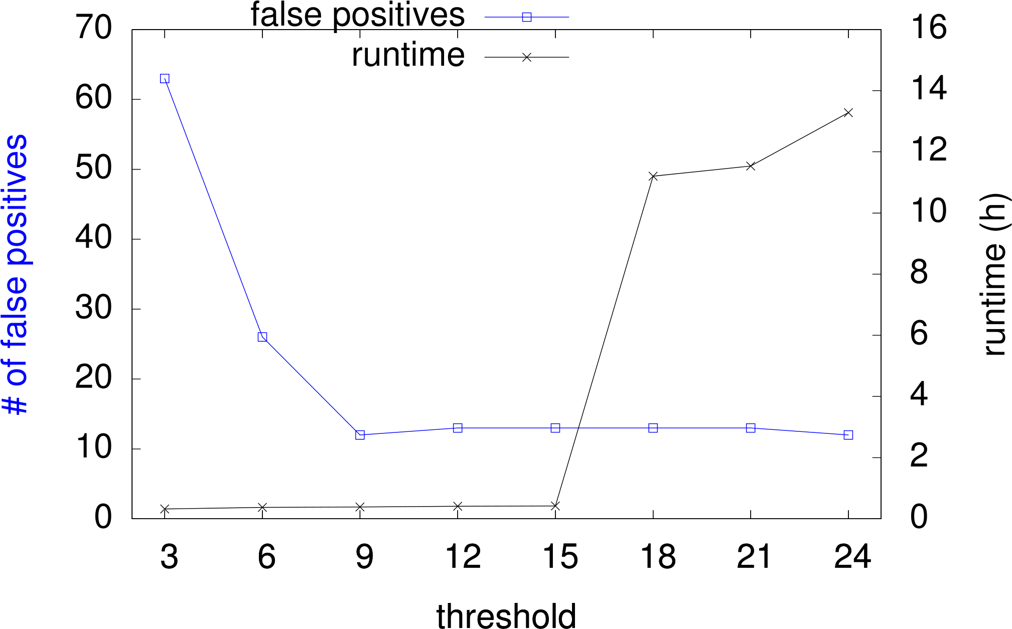
As the actual runtime of InFault depends on the choice of the threshold presented in ‘Splitting algorithm,’ we tested several threshold values to determine the speed of the algorithm. In general, smaller thresholds result in shorter runtimes with the drawback of more false positive alerts because of voters that have been broken during subgraph splitting. False positives have to be analyzed by manual graph inspection, or with other means. Figure 6 shows how overall runtime and number of false positives vary with increasing threshold, for all nine netlists of the LEON2-FT processor, with a total 19218 FFs and 570959 gates.
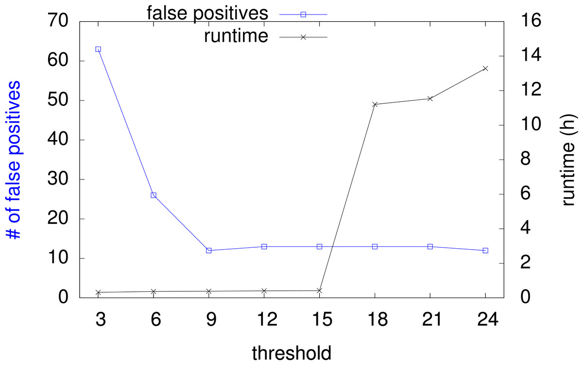
Figure 6: Runtime and false positive count with increasing threshold.
The sum of false positives for all nine given designs goes from 63 down to 12. The overall runtime goes from 19 min up to 13 h. For a suggested threshold of 15, the runtime is around 25 min. Please note that the runtime strongly correlates to the internal structure of the design, especially the subgraph sizes, and therefore it is subject to fluctuations among the designs.
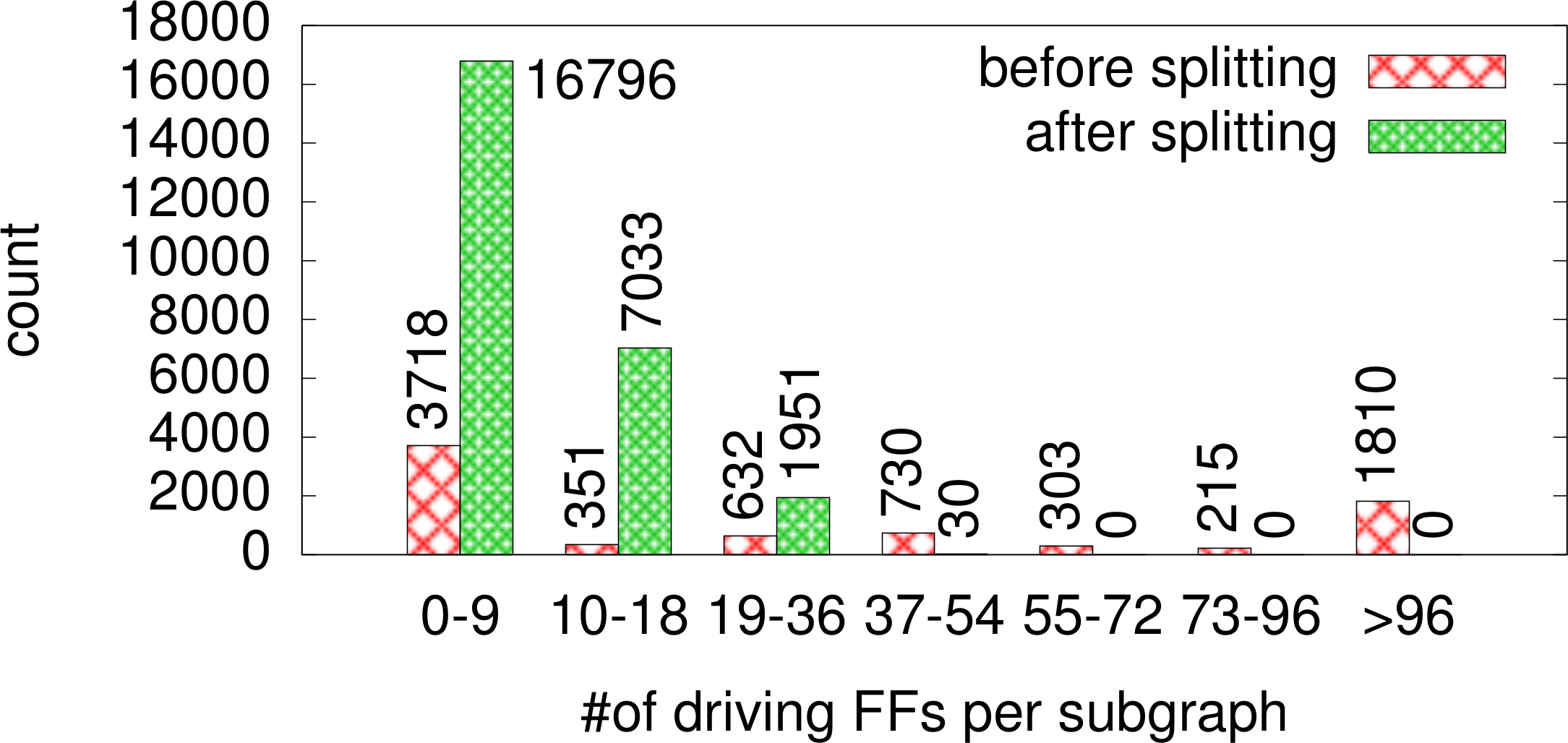
To show the effectiveness of the subgraph splitting, the algorithm was tested on the nine netlists, logging the different subgraph sizes before and after splitting (with threshold = 15). Figure 7 shows the results of this test. Before splitting, there are 1,810 subgraphs that consist of >96 driving gates. Assuming correct triplication this would result in more than 232 valid configurations to be checked for each of those nodes, making the splitting heuristic an essential component of our approach. In fact, after splitting the situation is completely different: even though the splitting results in many more subgraphs to be checked, the subgraph sizes are much smaller. There are no subgraphs with more than 54 driving gates, giving no more than 218 valid configurations.
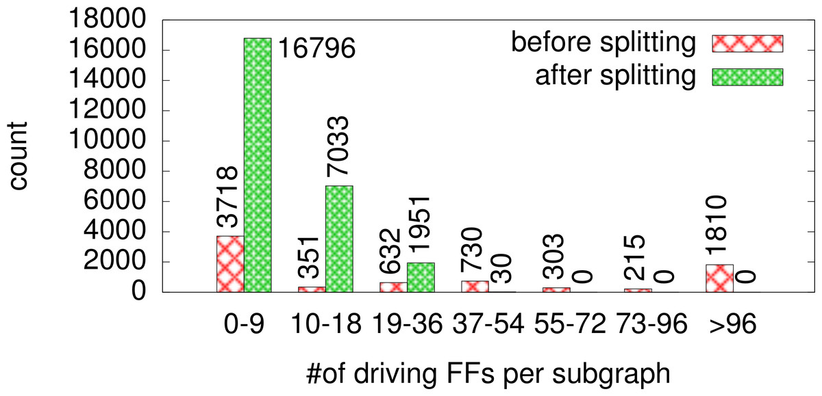
Figure 7: Size classification of subgraphs before and after splitting.
It is worth noting that the results depend on the complexity of the circuit, since the splitting algorithm effectiveness varies by the number of driving FFs. InFault might not have the same performance with other processors with very complex multi-layer logic.
To show its fault detecting capabilities, InFault was verified on a netlist (module iu in Table 1) with broken voters. The netlist used for this test consists of 1,408 triplets (4224 FFs). For the test run 898 triplets were automatically selected, and their voters manipulated by changing the voter function from to This should result in n = 898 ⋅ 3 SEU-sensitive FFs being detected. InFault reported problems in n = 899 ⋅ 3 FFs: all unprotected triplets plus one false positive. Finally, the methodology was applied to a production netlist of the LEON2-FT processor that reported failures due to SEUs after manufacturing, during a radiation test campaign. The algorithm reported 351 common reset lines for triplicated FFs. An SEU on these lines is consistent with the behaviour shown by the processor during radiation testing. These errors were introduced by the automated tools in charge of inserting TMR structures in the LEON2-FT processor, during the optimization phase. After correcting the netlist, with the proposed methodology reporting no remaining issue, the processor was irradiated further. Radiation tests showed no additional problems due to the TMR implementation, so that we can reasonably assume that the 351 flip-flops were the cause of the initial testing issues.
| Testcase | # gatesa | # FFs | FT-Ub time | InFault time (th-15) | InFault time (th-21) | FPc |
|---|---|---|---|---|---|---|
| Resetgen | 648 | 30 | 8h | <1m | <1m | 0 |
| pci mas | 14,379 | 453 | 5d 5h | <1m | 2m | 0 |
| pci tar | 13,768 | 546 | 6d 7h | <1m | 10m | 0 |
| mctrl | 35,357 | 1,251 | 14d 11h | 1m | 1m | 0 |
| fpu | 66,967 | 1,437 | 16d 15h | 10m | 10m | 6 |
| amod | 87,193 | 3,303 | 38d 5h | 1m | 3m | 2 |
| iu | 147,894 | 4,224 | 48d 21h | 8m | 406m | 3 |
| pci | 190,987 | 7,974 | 92d 7h | 4m | 264m | 2 |
Conclusions & Future Work
In this work we presented an algorithm to verify TMR implementation for given netlists. Performing exhaustive verification without the need of a testbench, this approach does not suffer from the quality and coverage of the given testbench as in other solutions. First results show that exhaustive TMR verification of production-ready netlists can be carried out within few hours. To the best of the authors’ knowledge, no other approach provides this kind of performance.
Future work includes replacing the actual simulation/injection step with the identification of triplets followed by formal verification of the correct propagation of flip-flop values through the voting logic.